
Once you have a cloud platform with virtual machines, network and storage, you will sooner or later want to expose services running on your platform to the outside world. The natural way to do this is to use a load balancer, and in a cloud, you of course want to utilize a virtual load balancer. For OpenStack, the Octavia project provides this as a service, and in todays post, we will take a look at Octavias architecture and learn how to install it.
Octavia components
When designing a virtual load balancer, one of the key decisions you have to take is where to place the actual load balancer functionality. One obvious option would be to spawn software load balancers like HAProxy or NGINX on one of the controller nodes or the network node and route all traffic via those nodes. This approach, however, has the clear disadvantage that it introduces a single point of failure (unless, of course, you run your controller nodes in a HA setup) and, even worse, it puts a load of load on the network interfaces of these few nodes, which implies that this solution does not scale well when the number of virtual load balancers or endpoints increases.
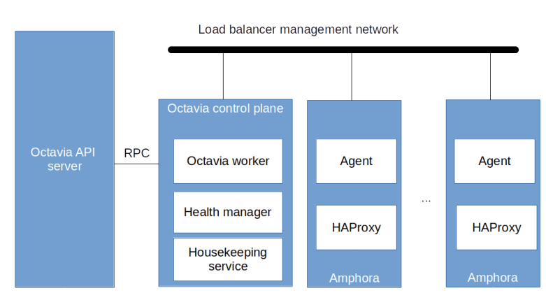
Octavia chooses a different approach. The actual load balancers are realized by virtual machines, which are ordinary OpenStack instances running on the compute nodes, but use a dedicated image containing a HAProxy software load balancer and an agent used to control the configuration of the HAProxy instance. These instances – called the amphorae – are therefore scheduled by the Nova scheduler as any other Nova instances and thus scale well as they can leverage all available compute nodes. To control the amphorae, Octavia uses a control plane which consists of the Octavia worker running the logic to create, update and remove load balancers, the health manager which monitors the amphorae and the house keeping service which performs clean up activities and can manage a pool of spare amphorae to optimize the time it takes to spin up a new load balancer. In addition, as any other OpenStack project, Octavia exposes its functionality via an API server.
The API server and the control plane components communicate with each other using RPC calls, i.e. RabbitMQ, as we have already seen it for the other OpenStack services. However, the control plane components also have to communicate with the amphorae. This communication is bi-directional.
- The agent running on each amphora exposes a REST API that the control plane needs to be able to reach
- Conversely, the health manager listens for health status messages issued by the amphorae and therefore the control plane needs to be reachable from the amphorae as well
To enable this two-way communication, Octavia assumes that there is a virtual (i.e. Neutron) network called the load balancer management network which is specified by the administrator during the installation. Octavia will then attach all amphorae to this network. Further, Octavia assumes that via this network, the control plane components can reach the REST API exposed by the agent running on each amphora and conversely that the agent can reach the control plane via this network. There are several ways to achieve this, we get back to this point when discussing the installation further below. Thus the overall architecture of an Octavia installation including running load balancers is as in the diagram below.
Octavia installation
Large parts of the Octavia installation procedure (which, for Ubuntu, is described here in the official documentation) is along the lines of the installation procedures for other OpenStack components that we have already seen – create users, database tables, API endpoints, configure and start services and so forth. However, there are a few points during the installation where I found that the official documentation is misleading (at the least) or where I had problems figuring out what was going on and had to spend some time reading source code to clarify a few things. Here are the main pitfalls.
Creating and connecting the load balancer management network
The first challenge is the setup of the load balancer network mentioned before. Recall that this needs to be a virtual network to which our amphorae will attach which allows access to the amphorae from the control plane and allows traffic from the amphorae to reach the health manager. To build this network, there are several options.
First, we could of course create a dedicated provider network for this purpose. Thus, we would reserve a physical interface or a VLAN tag on each node for that network and would set up a corresponding provider network in Neutron which we use as load balancer management network. Obviously, this only works if your physical network infrastructure allows for it.
If this is not the case, another option would be to use a “fake” physical network as we have done it in one of our previous labs. We could, for instance, set up an OVS bridge managed outside of Neutron on each node, connect these bridges using an overlay network and present this network to Neutron as a physical network on which we base a provider network. This should work in most environments, but creates an additional overhead due to the additionally needed bridges on each node.
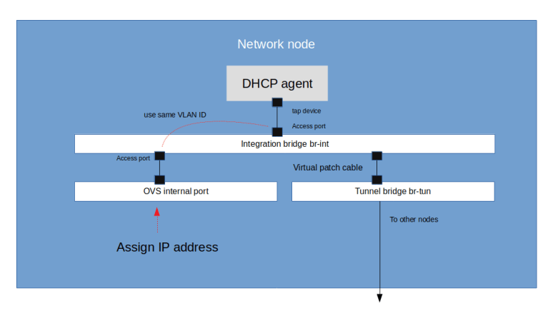
Finally – and this is the approach that also the official installation instructions take – we could simply use a VXLAN network as load balancer management network and connect to it from the network node by adding an additional network device to the Neutron integration bridge. Unfortunately, the instructions provided as part of the official documentation only work if Linux bridges are used, so we need to take a more detailed look at this option in our case (using OVS bridges).
Recall that if we set up a Neutron VXLAN network, this network will manifest itself as a local VLAN tag on the integration bridge of each node on which a port is connected to this network. Specifically, this is true for the network node, on which the DHCP agent for our VXLAN network will be running. Thus, when we create the network, Neutron will spin up a DHCP agent on the network node and will assign a local VLAN tag used for traffic belonging to this network on the integration bridge br-int.
To connect to this network from the network node, we can now simply bring up an additional internal port attached to the integration bridge (which will be visible as a virtual network device) and configured access port, using this VLAN tag. We then assign an IP address to this device, and using this IP address as a gateway, we can now connect to every other port on the Neutron VXLAN network from the network node. As the Octavia control plane components communicate with the Octavia API server via RPC, we can place them on the network node so that they can use this interface to communicate with the amphorae.
With this approach, the steps to set up the network are as follows (see also the corresponding Ansible script for details).
- Create a virtual network as an ordinary Neutron VXLAN network and add a subnet
- Create security groups to allow traffic to the TCP port on which the amphora agent exposes its REST API (port 9443 by default) and to allow access to the health manager (UDP, port 5555). It is also helpful to allow SSH and ICMP traffic to be able to analyze issues by pinging and accessing the amphorae
- Now we create a port on the load balancer network. This will reserve an IP address that we can use for our port to avoid IP address conflicts with Neutron
- Then we wait until the namespace for the DHCP agent has been created, get the ID of the corresponding Neutron port and read the VLAN tag for this port from the OVS DB (I have created a Jinja2 template to build a script doing all this)
- Now create an OVS access port using this VLAN ID, assign an IP address to the corresponding virtual network device and bring up the device
There is a little gotcha with this configuration when the OVS agent is restarted, as in this case, the local VLAN ID can change. Therefore we also need to create a script to refresh the configuration and run it via a systemd unit file whenever the OVS agent is restarted.
Image creation
The next challenge I was facing during the installation was the creation of the image. Sure, Octavia comes with instructions and a script to do this, but I found some of the parameters a bit difficult to understand and had to take a look at the source code of the scripts to figure out what they mean. Eventually, I wrote a Dockerfile to run the build in a container and corresponding instructions. When building and running a container with this Dockerfile, the necessary code will be downloaded from the Octavia GitHub repository, some required tools are installed in the container and the image build script is started. To have access to the generated image and to be able to cache data across builds, the Dockerfile assumes that your local working directory is mapped into the container as described in the instructions.
Once the image has been built, it needs to be uploaded into Glance and tagged with a tag that will also be added to the Octavia configuration. This tag is later used by Octavia when an amphora is created to locate the correct image. In addition, we will have to set up a flavor to use for the amphorae. Note that we need at least 1 GB of RAM and 2 GB of disk space to be able to run the amphora image, so make sure to size the flavor accordingly.
Certificates, keys and configuration
We have seen above that the control plane components of Octavia use a REST API exposed by the agent running on each amphora to make changes to the configuration of the HAProxy instances. Obviously, this connection needs to be secured. For that purpose, Octavia uses TLS certificates.
First, there is a client certificate. This certificate will be used by the control plane to authenticate itself when connecting to the agent. The client certificate and the corresponding key need to be created during installation. As the CA certificate used to sign the client certificate needs to be present on every amphora (so that the agent can use it to verify incoming requests), this certificate needs to be known to Octavia as well, and Octavia will distribute it to each newly created amphora.
Second, each agent of course needs a server certificate. These certificates are unique to each agent and are created dynamically at run time by a certificate generator built into the Octavia control plane. During the installation, we only have to provide a CA certificate and a corresponding private key which Octavia will then use to issue the server certificates. The following diagram summarizes the involved certificates and key.

In addition, Octavia can place an SSH key on each amphora to allow us to SSH into an amphora in case there are any issues with it. And finally, a short string is used as a secret to encrypt the health status messages. Thus, during the installation, we have to create
- A root CA certificate that will be placed on each amphora
- A client certificate signed by this root CA and a corresponding client key
- An additional root CA certificate that Octavia will use to create the server certificates and a corresponding key
- An SSH key pair
- A secret for the encryption of the health messages
More details on this, how these certificates are referenced in the configuration and a list of other relevant configuration options can be found in the documentation of the Ansible role that I use for the installation.
Versioning issues
During the installation, I came across an interesting versioning issue. The API used to communicate between the control plane and the agent is versioned. To allow different versions to interact, the client code used by the control plane has a version detection mechanism built into it, i.e. it will first ask the REST API for a list of available versions and then pick one based on its own capabilities. This code obviously was added with the Stein release.
When I first installed Octavia, I used the Ubuntu packages for the Stein release which are part of the Ubuntu Cloud archive. However, I experienced errors when the control plane was trying to connect to the agents. During debugging, I found that the versioning code is present in the Stein branch on GitHub but not included in the version of the code distributed with the Ubuntu packages. This, of course, makes it impossible to establish a connection.
I do not know whether this is an archiving error or whether the versioning code was added to the Stein maintenance branch after the official release had gone out. To fix this, I now pull the source code once more from GitHub when installing the Octavia control plane to make sure that I run the latest version from the Stein GitHub branch.
Lab 14: adding Octavia to our OpenStack playground
After all this theory, let us now run Lab14, in which we add Octavia to our OpenStack playground. Obviously, we need the amphora image to do this. You can either follow the instructions above to build your own version of the image, or you can use a version which I have built and uploaded into an S3 bucket. The instructions below use this version.
So to run the lab, enter the following commands (assuming, as always in this series, that you have gone through the basic setup described here).
git clone https://www.github.com/christianb93/openstack-labs
cd openstack-labs/Lab14
wget https://s3.eu-central-1.amazonaws.com/cloud.leftasexercise.com/amphora-x64-haproxy.qcow2
vagrant up
ansible-playbook -i hosts.ini site.yaml
In the next post, we will test this setup by bringing up our first load balancer and go through the configuration and provisioning process step by step.

1 Comment