The nuts and bolts of VertexAI – networking

When we access a VertexAI predicition endpoint, we usually do this using the Google API endpoint, i.e. we access a public IP address. For some applications, it is helpful to be able to connect to a prediction endpoint via a private IP address from within a VPC. Today, we will see how this works and how the same approach allows you to also connect to an existing VPC from within a pipeline job.

VPC Peering

The capability of the Google cloud platform that we will have to leverage to establish a connection between VertexAI services and our own VPCs is called VPC peering, so let us discuss this first.

Usually, two different networks are fully isolated, even if they are part of the same project. Each network has its own IP range, and virtual machines running in one network cannot directly connect to virtual machines in another network. VPC peering is a technology that Google offers to bridge two VPCs by adding appropriate routes between the involved subnets.

To understand this, let us consider a simple example. Suppose you have two networks, say vpc-a and vpc-b, with subnets subnet-a (range 10.200.0.0/20) and subnet-b (10.210.0.0/20).

Google will then establish two routes in each of the networks. The first route called the default route sends all traffic to the gateway that connects the VPC with the internet. The second route called the subnet route (which exists for every subnet) has a higher priority and makes sure that traffic to a destination address within the IP address range of the respective subnet is delivered within the VPC.

As expected, there is not route that is connecting the two networks. This is changed if you decide to peer the two networks. Peering sets up additional routes in each of the networks so that traffic targeting a subnet in the respective peer network is routed into this network, thus establishing a communication channel between the two networks. If, in our example, you peer network-a and network-b, then a route will be set up for network-a that sends traffic with destination in the range 10.210.0.0/20 to network-b and vice versa. Effectively, we map subnet-b into the IP address space of network-a and subnet-a into the IP address space of network-b.

Note that peering is done on the network level and applies for all subnets of both networks involved. As a consequence, this can only work if the address ranges of the subnets in both networks do not overlap, as we would otherwise produce conflicting routes. This is the reason why peering does not work with networks created in auto-mode, but requires subnet mode custom.

Private prediction endpoints

Let us now see how VPC peering can be applied to access prediction endpoints from within your VPC using a private IP address. Obviously, we need a model to do this that we can deploy. So follow the steps in our previous post on models to upload a model to the Vertex AI registry (i.e. train a model, create an archive, upload the archive to GCS and the model to the registry) with ID vertexaimodel.

Next we will deploy the model. Recall that the process of deploying a model consists of two steps – creating and endpoint and deploying the model to this endpoint. When we want to deploy a model that can be reached from within a VPC, we will need to create what Google calls a private endpoint instead of an endpoint. This is very similar to an endpoint, with the difference that as an additional parameter, we need to pass the name of a VPC. Behind the scenes, Google will then create a peering between the network in which the endpoint is running and our VPC, very similar to what we have done manually in the previous section.

For this to work, we first need a few preparations. First, we need to set up our VPC, and we also create a few firewall rules that allow SSH access to machines running in this network (which we will need later), and allow ICPM and internal traffic.

gcloud compute networks create peered-network \
                        --subnet-mode=custom
gcloud compute firewall-rules create peered-network-ssh \
                                --network peered-network \
                                --allow tcp:22
gcloud compute firewall-rules create peered-network-icmp \
                                --network peered-network \
                                --allow icmp
gcloud compute firewall-rules create peered-network-internal \
                                --network peered-network \
                                --source-ranges=10.0.0.0/8 \
                                --allow tcp 

Now we need to let Google know which IP address range it can use to establish a peering. This needs to be a range that we do not actively use. To inform Google about our choice, we create an address range with the special purpose VPC_PEERING. We also need to create a peering between our network and the service network that Google uses.

gcloud compute addresses create peering-range \
    --global \
    --purpose=VPC_PEERING \
    --addresses=10.8.0.0 \
    --prefix-length=16 \
    --network=peered-network
gcloud services vpc-peerings connect \
    --service=servicenetworking.googleapis.com \
    --network=peered-network \
    --ranges=peering-range \
    --project=$GOOGLE_PROJECT_ID

To create a private endpoint and deploy our model to it, we can use more or less the same Python code that we have used for an ordinary endpoint, except that we create an instance of the class PrivateEndpoint instead of Endpoint and pass the network to which we want to peer as additional argument (note, however, that private endpoints do currently not support traffic splitting, so the parameters referring to this are not allowed).

endpoint = aip.PrivateEndpoint.create(
    display_name = "vertex-ai-private-endpoint",
    project = google_project_id, 
    location = google_region,
    network = f"projects/{project_number}/global/networks/{args.vpc}"
)

Let us try this – simply navigate to the directory networking in the repository for this series and execute the command

python3 deploy_pe.py --vpc=peered-network

Again this will probably take some time, but the first step (creating the endpoint) should only take a few seconds. Once the deployment completes, we should be able to run predictions from within our VPC. To be able to verify this, let us next bring up a virtual machine in our VPC, more precisely within a subnet inside our VPC that we need to create first. For that purpose, set the environment variable GOOGLE_ZONE to your preferred zone within the region GOOGLE_REGION and run

gcloud compute networks subnets create peered-subnet \
       --network=peered-network \
       --range=10.210.0.0/20 \
       --purpose=PRIVATE \
       --region=$GOOGLE_REGION
gcloud compute instances create client \
       --project=$GOOGLE_PROJECT_ID \
       --zone=$GOOGLE_ZONE \
       --machine-type=e2-medium \
       --network=peered-network \
       --subnet=peered-subnet \
       --create-disk=boot=yes,device-name=instance-1,image-family=ubuntu-2204-lts,image-project=ubuntu-os-cloud

Next, we need to figure out under which network address our client can reach the newly created endpoint. So run gcloud ai endpoints list to find the ID of our endpoint and then use gcloud ai endpoints describe to print out some details. In the output, you will find a property called predictHttpUri. Take note of that address, which should be a combination of the endpoint ID, the domain aiplatform.googleapis.com and the ID of the model. Then SSH into our client machine and run a curl against that address (set URL in the command below to the address that you have just noted).

gcloud compute ssh client --zone=$GOOGLE_ZONE
URL=...
curl \
        --data '{"instances": [ [0.5, 0.35]]}' \
        --header "Content-Type: application/json" $URL

At first glance, this seems to be very similar to a public endpoint, but there are a few notable differences. First, you can use getent hosts in the client machine to convince yourself that the DNS name in the URL that we use does in fact resolve to a private IP address in the range that we have defined for the peering (when I tried this, I got 10.8.0.6, but the result could of course be different in your case). We can even repeat the curl command and use the IP address instead of the DNS name, and we should get the same result.

The second thing that is interesting here is we did not have to associate our virtual machine with any service account. In fact, everyone who has access to your VPC can invoke the endpoint, and there is no additional permission check. This is in contrast to a public endpoint which can only be reached when passing a bearer token in the request. So you might want to be very thoughtful about who has access to your network before deploying a model to a private endpoint – this is in fact not private at all.

We also remark that creating a private endpoint is not the only way to reach a prediction endpoint via a private IP address. The alternative approach that Google offers you is called private service connect which provides a Google API endpoint at an IP address in your VPC. You can then deploy a model as usual to an ordinary endpoint, but use this private access point to run predictions.

Connecting to your VPC from a VertexAI pipeline

So far, we have seen how we can reach a prediction endpoint from within our VPC using a peering between the Google service network and our VPC. However, this also works in the other direction – once we have the peering in place, we can also reach a service running in our VPC from within jobs and pipelines running on the VertexAI platform.

Let us quickly discuss how this works for a pipeline. Again, the preconditions that you need are as above – a VPC, a reserved IP address range in that VPC and a peering between your VPC and the Google service network.

Once you have that, you can build a pipeline that somehow accesses your VPC, for instance by submitting a HTTP GET request to a server running in your VPC. When you submit this job, you need to specify the additional parameter network as we have done it when creating our private endpoint. In Python, this would look as follows.

#
# Make sure that project_number is the number (not the ID) of the project 
# you are using
#
project_number = ...
#
# Create a job
#
job = aip.PipelineJob(
    display_name = "Connectivity test pipeline",
    template_path = "connect.yaml",
    pipeline_root = pipeline_root,
    location = location,
)    

#
#
# Submit the job
job.submit(service_account = service_account, 
           networkm= f"projects/{project_number}/global/networks/{args.vpc}")

Again, this will make Vertex AI use the peering to connect the running job to your network so that you can access the server. I encourage you to try this out, just modify any of the pipelines we have discussed in our corresponding post to submit a HTTP request to a simple Flask server or an NGINX instance running in your VPC to convince yourself that this really works.

This closes our post for today. Next time, we will take a look at how you can use Vertex AI managed datasets to organize your training data.
The nuts and bolts of VertexAI – pipeline metadata

When you assemble and run a custom job, the Vertex AI platform is not aware of the inputs that you consume and the outputs that you create in this job, and consequently, it is up to you to create execution and artifact metadata and the corresponding relations between executions, input artifacts and output artifacts. For pipelines, the situation is different, as you explicitly declare input and output artifact of each component that is executed as part of a pipeline. Thus you could expect that the platform takes over the task to reflect this in the metadata, and in fact it does. Today, we take a closer look at the metadata that a pipeline run produces.

Pipeline jobs, executions and artifacts

As a starting point for what follows, let us first conduct a little experiment. Starting from the root directory of the cloned repository run the following commands to clean up existing metadata (be careful, this will really delete all metadata in your Vertex AI project) and submit a pipeline.

cd pipelines
python3 ../metadata/list_metadata.py --delete
python3 submit_pipeline.py

Then wait a few minutes until the pipeline run is complete and display the metadata that this pipeline run has created.

python3 ../metadata/list_metadata.py --verbose

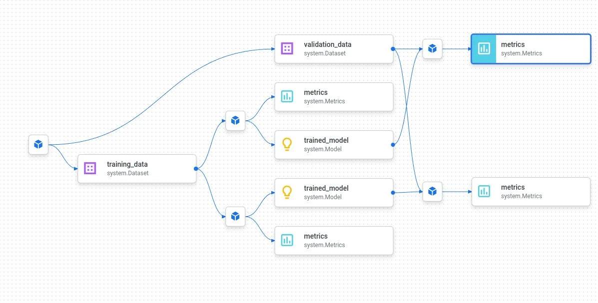
We can see that Vertex AI will create a couple of metadata objects automatically. First, we see artifacts representing the input and outputs of our components, like the model, the test and validation data and the metrics that we log. Then we see one execution of type system.ContainerExecution for each component that is being executed, and the artifacts are correctly linked to these executions.

There is also an execution of type system.Run that apparently represents the pipeline run. Its metadata contains information like the project and the pipeline run ID, but also the parameters that we have used when submitting the pipeline.

Finally, Vertex AI will create two nested contexts for us. The first context is of type system.PipelineRun and represents the run. All executions and artifacts for this run are living inside this context. In addition, there is a context which represents the pipeline (type system.Pipeline) and the pipeline run is a child of this context. When we submit another run of the pipeline, then a new run context will be created and will become a child of this pipeline context as well. Here is a diagram summarizing the structure that we can see so far.

Experiment runs and pipelines

Let us now see how this changes if we specify an experiment when submitting our pipeline (the submit method of the PipelineJob has a corresponding parameter). In this case, the SDK will locate the pipeline run context and associate it with the experiment, i.e. it will add it as child to the metadata context that represents the experiment. Thus our pipeline run context has two parent contexts – the context representing the experiment and the context representing the pipeline. Let us try this.

python3 ../metadata/list_metadata.py --delete
python3 submit_pipeline.py --experiment=my-experiment
#
# Wait until completion
#
python3 ../metadata/list_metadata.py --verbose

This should give an output reflecting the following diagram.

If you now open the Vertex AI console and navigate to the “Experiments” tab, you will see our newly created experiment and inside this experiment, there is a new run (the name of this run is a combination of the pipeline name and a timestamp). You can also see that the metadata that is attached to the pipeline execution, in particular the input parameters, show up as parameters, and that all metrics that we log using log_metric on an artifact of type Metric will automatically be displayed in the corresponding tab for the pipeline run. So similar to what we have seen for custom jobs, you again have a central place from which you can access parameters, metrics and even the artifacts created during this pipeline run. However, this time our code inside the pipeline components does not have to use any reference to the Google cloud framework, we only interact with the KFP SDK, which makes local execution and unit testing a lot easier.

Using tensorboards with Vertex AI pipelines

We have seen that logging individual metrics from within a pipeline is very easy – just add an artifact of type Metrics to your component and call log_metrics on that, and Vertex AI will make sure that the data appears on the console. However, for time series, this is more complicated, as Vertex AI pipeline are apparently not yet fully integrated with the Vertex AI tensorboards.

What options do we have if we want to log time series data from within a component? One approach could be to simply use start_run(..., resume = True) to attach to the pipeline run and then log time series data as we have done it from within a custom job. Unfortunately, that does not work, as start_run assumes that the run you are referring to is of type system.ExperimentRun but our run is of type system.PipelineRun.

You could of course create a new experiment run and use that experiment run to log time series data. This works, but has the disadvantage that now every run of the pipeline will create two experiment runs on the console, which is at least confusing. Let us therefore briefly discuss how to use the tensorboard API directly to log data.

The tensorboard API is built around three main classes – a Tensorboard , a TensorboardExperiment and a TensorboardRun. A Tensorboard is simply that – an instance of a managed tensorboard on Vertex AI. Usually there is no need to create a tensorboard instance manually, as Vertex AI will make sure that there is a backing tensorboard if you create an experiment in the init function (the default is to use the same tensorboard as backing tensorboard for all of your experiments). You can access this tensorboard via the backing_tensorboard_resource_name attribute of an Experiment.

Once you have access to the tensorboard instance, the next step is to create a tensorboard experiment. I am not sure how exactly Google has implemented this behind the scenes, but I tend to think of a tensorboard experiment as a logging directory in which all event files will be stored. If you make sure that the name of a tensorboard experiment matches the name of an existing Vertex AI experiment, then a link to the tensorboard will be displayed next to the experiment in the Vertex AI console. In addition, I found that there is a special label vertex_tensorboard_experiment_source that you will have to add with value vertex_experiment to avoid that the tensorboard experiment is displayed as a separate line in the list of experiments.

Next, you will need to create a tensorboard run. This is very similar to an experiment run and – at least in a local tensorboard installation – corresponds to a directory in the logging dir where event files are stored.

If you actually want to log time series data, you will do so by passing a label, for instance “loss”, a value and a step. Label and value are passed as a dictionary, the step is an integer, so that a call looks like this.

#
# Create a tensorboard run
#
tb_run = ...
#
# Log time series data to it
# 
tb_run.write_tensorboard_scalar_data({
                            "loss" : 0.05
                        }, step = step)

All values with the same label – in our case “loss” – form a time series. However, before you can log data to a time series in this way, you will actually have to create a time series within the tensorboard run. This is a bit more complicated than it sounds as creating a time series that already exists will fail, so you need to check upfront whether the time series exists. To reduce the number of API calls needed, you might want to keep track of which time series have already been created locally.

In order to simplify the entire process and in order to allow for easier testing, I have put all of this into a utility class defined here. This class can be initialized once with the name of the experiment you want to use, a run name and your project ID and location and then creates the required hierarchy of objects behind the scenes. Note, however, that logging to a tensorboard is slow (I assume that the event file is stored on GCS so that appending a record is an expensive operation), so be careful not to log too many data points. In addition, even though our approach works well and gives you a convenient link to your time series in the Vertex AI console, the data you are logging in this way is not visible in the embedded view which is part of the Vertex AI console, but only in the actual tensorboard instance – I have not yet figured out how to make the data appear in the integrated view as well.

The standard pipeline that we use for our tests already uses tensorboard logging in this way if you submit it with an experiment name as above. Here is how the tensorboard instance will look like once the training step (which logs the training loss) is complete.

Some closing remarks

Pipeline metadata is a valuable tool, but does not mean that you do not have to implement additional mechanisms to allow for full traceability. If, for instance, you train a model on a dataset that you download from some location in your pipeline and then package and upload a new model version, the pipeline metadata will help you to reconstruct the pipeline run, but the entry in the model registry has no obvious link to the pipeline run (unless maybe the URI which will typically be some location inside the pipeline root), you will still need to track the version of your Python code for defining the model and the training script separately, and you can also not rely on the pipeline metadata alone to document the version of data you use that originates from outside of Vertex AI.

I tend to think of pipeline metadata as a tool which is great for training – you can conduct experiment runs, attach metrics and evaluation results to runs, compare results across runs and so forth – but as soon as you deploy to production, you will need additional documentation.

You might for instance want to create a model card that you add to your model archive. This model card can be assembled as a markdown or HTML artifact inside your pipeline declared as component output via Output[Markdown](VertexAI will even display the model card artifact for you).

Of course this is just a toy example, and in general you might want to use a toolkit like the Google Model Card Toolkit to assemble your model card, typically using metadata and metrics that you have collected during your pipeline run. You can then distribute the model card to a larger group without depending on access to Vertex AI metadata and archive it, maybe even in your version control system.

Vertex AI metadata is also comparatively expensive. At the time of writing, Google charges 10 USD per GB and month. Even standard storage at european locations is around 2 cents per GB and month, and archive storage is even less expensive. So from time to time, you want to clean up your metadata store and archive the data. As an example of how this could work, I have provided a script cleanup.py in the pipelines directory of my repository. This script removes all metadata (including experiments) as well as pipeline runs and custom job executions older than a certain number of days. In addition, you can chose to archive the artifact lineage into a file. Here is an example which will remove all data older than 5 days and write the lineage information into archive.dat.

python3 cleanup.py --retention_days=5 --archive=archive.dat

This closes our blog post for today. In the next post, we will turn our attention away from pipelines to networking and learn how you can connect jobs running on Vertex AI to your own VPCs and vice versa.

The nuts and bolts of VertexAI – pipelines under the hood

In our previous post, we have covered the process of creating pipeline components, defining a pipeline and running the pipeline in Vertex AI. However, parts of this appeared to be a bit mysterious. Today, we will take a closer look at what is going on behind the scenes when we create and run a pipeline

Deep dive into component creation

To be able to easily and interactively inspect the various types of Python objects involved, an interactive Python shell is useful. You might want to use ipython3 for that purpose or you might want to run the following commands to install a kernel into our environment and add the kernel to the Jupyter configuration so that you can run all this in a Jupyter notebook.

pip3 install ipykernel
python -m ipykernel install --user --name=vertexai-venv

As a starting point for our discussion, it is helpful to recall what a Python decorator is doing. Essentially, a decorator is a device to wrap a function into a different function or – more precisely – a callable which can either be a function or a Python object with a __call__ method. Therefore, a decorator is a function which accepts a function as input and returns a callable. This callable will then be registered under the name of the original function in the namespace, so effectively replacing the decorated function by the new callable.

Let us take a closer look at this for the example of a pipeline component. Suppose we have a very simply pipeline component.

from kfp import dsl 
from kfp.dsl import Output, Artifact, Dataset

@dsl.component(base_image = "python:3.9")
def my_component(msg : str, data : Output[Dataset]):
    print(f"Message: {msg}")

When the Python interpreter hits upon this piece of code, it will call the decorator – i.e. the function kfp.dsl.component_decorator.component– with the first argument being your my_component function (and the remaining parameters being the parameters of the decorators like base_image in our case). This decorator function uses inspection to analyze the parameters of your function and then returns an instance of kfp.dsl.python_component.PythonComponent which then becomes known under the name my_component . Let us verify this in our interactive Python session and learn a bit about our newly created object.

type(my_component)
my_component.__dict__.keys()

We see that our new object has an attribute python_func. This is in fact the wrapped function which you can inspect and run.

import inspect
inspect.getsource(my_component.python_func)
my_component.python_func("Hello", data = None)

Another interesting attribute of our object is the component_spec. This contains the full specification of the container that will implement this component (you might want to take a look at this, but we will get back to it later) including image, command, arguments and environment, and the description of inputs and outputs of our component.

Assembling a pipeline

We now have a component. As a next step, we will assemble our components into a pipeline. As we have seen, this usually happens with a piece of code like this.

@dsl.pipeline()
def my_pipeline():
    _task = my_component(msg = "Hello")

So here we call our component – but in fact, as our component has been replaced by the PythonComponent, we do actually not call our component but end up in the __call__ method of PythonComponent. This method will create a representation of the component at runtime, i.e. an instance of a PipelineTask. In addition to a component specification, this object now also contains the inputs and outputs of our component (we see actual values, not just descriptions – note that artifacts are represented by placeholders).

_task = my_component(msg = "Hello")
print(type(_task))
print(_task.component_spec)
print(_task.inputs)
print(_task.outputs)

But how do the components actually end up in a pipeline? Why is there no need to explicitly call something along the lines of my_pipeline.add(my_component)? This is where the magic of decorators and the magic of context managers join forces…

To understand this, let us go back a step and think about what happens when the Python interpreter hits upon the line @dsl.pipeline. At this point, the pipeline decorator function defined here is invoked and receives our function my_pipeline as argument. After some intermediate calls, we end up constructing a GraphComponent which is the object actually representing a pipeline. In the constructor of this component, we find the following code snippet.

with pipeline_context.Pipeline(
                self.component_spec.name) as dsl_pipeline:
    pipeline_outputs = pipeline_func(*args_list)

So we eventually run the code inside the function body of our my_pipeline function where, as we already know, we create a PipelineTask for every component. But we do this within a pipeline context, i.e. an instance of the class Pipeline which implements the Python context manager interface. So the __enter__ method is called, and this method sets the variable pipeline_task.PipelineTask._register_task_handler.

Now the point is that the function pointed to by this variable is invoked in the constructor of a PipelineTask (this happens here)! Thus for every component created inside a function that carries the pipeline decorator, a call into the pipeline context, more precisely into the add_task method of the pipeline context, will be made automatically, meaning that all components that we create here will automatically be registered with the pipeline. Its not magic, just some very clever Python code…

We can now also understand why a syntax like

_train = train(epochs = epochs,lr = lr)
evaluate(trained_model = _train.outputs['trained_model'])

for connecting inputs and outputs works. When this is executed, _train is an instance of a PipelineTask which does actually have an attribute called outputs, and we have seen that this is a dictionary with one entry for each output that we declare. This explains why we can get the outputs from this dictionary and pass them another component as input.

An important lesson from all this is that the code in the pipeline definition gets executed at build time, but the code in the component definition is actually never executed unless we submit the pipeline. This implies that trivial errors in the code are detected only if you really submit the pipeline (and this takes some time, as every step provisions a new container on the Google platform). Therefore it is vitally important to test your code locally before you submit it, we will see a bit later in this post how this can be done.

Pipeline execution

We have seen above that the component specification that is part of a Python component or a pipeline task does already contain the command (i.e. the entrypoint) and the arguments which will be used to launch the container. Structurally (and much simplified, if you want to see the full code take a look at the generated pipeline IR YAML file after compilation), this command in combination with the arguments looks as follows.

#
# First install KFP inside the container
#
python3 -m pip install kfp
#
# Create a Python module holding the code
# of the component
# 
printf "%s" <<code of your component>> > "ephemeral_component.py"
#
# Run KFP executor pointing to your component
#
_KFP_RUNTIME=true python3 -m kfp.dsl.executor_main \
  --component_module_path  "ephemeral_component.py" \
  --executor_input <<executor input>> \
  --function_to_execute <<your component code>>

Let us go through this step by step. First, we invoke pip to make sure that the KFP package is installed in the container (in the full version of the code, we can also see that apt-get is used to install pip if needed, which makes me think about what happens if we use a base image that is not based on a Debian distribution – I do not think that this implicit requirement is mentioned anywhere in the documentation). We then store the code of the pipeline component in a file called ephemeral_component.py, and run the KFP executor main entry point.

After loading your code as a module, this will create an instance of an executor and invoke its execute method. This executor is created with two arguments – the function to be executed (corresponding to the last argument in the command line sketched above) and the executor input (corresponding to the second to last line in the command above).

The executor input is a JSON structure that contains the information that the executor needs to construct input and output artifacts. Here is an example.

{
    "inputs": {
        "parameterValues": {
            "size": 1000
        }
    },
    "outputs": {
        "outputFile": "./gcs/create_data/execution_output.json",
        "artifacts": {
            "training_data": {
                "artifacts": [
                    {
                        "name": "training_data",
                        "metadata": {},
                        "type": {
                            "schemaTitle": "system.Dataset"
                        },
                        "uri": "gs://pipeline_root/create_data/training_data"
                    }
                ]
            },
            "validation_data": {
                "artifacts": [
                    {
                        "name": "validation_data",
                        "metadata": {},
                        "type": {
                            "schemaTitle": "system.Dataset"
                        },
                        "uri": "gs://pipeline_root/create_data/validation_data"
                    }
                ]
            }
        }
    }
}

In this example, the input only consists of parameters, but in general, the input section can also contain artifacts and would then look similarly to the output section.

In the output section, we can find a description of each artifact created by our component. This description contains all the fields (name, metadata, schema and URI) that are needed to instantiate a Python representation of the artifact, i.e. an instance of the Artifact class. In fact, this is what the executor does – it uses the data in the executor input to instantiate parameters and input and output artifacts and then simply calls the code of the component with that data. Inside the component, we can then access the artifacts and parameters as usual.

Note that the output section also contains an execution output file. This is a file to which the executor will log outputs. When you run a pipeline on Vertex AI, this executor output is stored in your GCS pipeline root directory along with the real artifacts. If your component returns any parameter values (a feature which we have mentioned but not yet discussed so far), the executor will add the output parameter values to this file as well so that the engine can get it from there if needed.

We can now understand what execution of a pipeline really means. The engine executing your pipeline needs to inspect the DAG derived from the pipeline to understand in what order the components needs to run. For each component, it then assembles the executor input and runs the container defined in the component specification with the command and arguments as sketched above. It then looks at the execution output written by the file and extracts the outputs of the components from there to be able to pass it as input to other components if needed.

There is one little step that we have not discussed so far. We have learned that an artifact has an URI (pointing to GCS) and a path (pointing into a local file system inside the container). How is the URI mapped to the path and why can the component code access the artifact?

Again, the source gives us a clue, this time the code of the Artifact class itself in which we see that the path attribute is decorated as a Python property, turning it into what the Python documentation calls a managed attribute. If you look at the underlying function, you will see that this simply translates the URI into a local path by replacing the “gs://” piece of the GCS location with “/gcs” (or whatever is stored in _GCS_LOCAL_MOUNT_PREFIX). The executing engine needs to make sure that this directory exists and contains a copy of the artifact, and that changes to that copy are – at least for output artifacts – replicated back to the actual object on GCS. Vertex AI does this by mounting the entire bucket using gcsfuse, but the KFP internal executor seems to simply create a copy at least if I read this code correctly)

Testing pipelines locally

Having a better understanding of what happens when a component is executed now puts in a position to think about how we can execute a component locally for testing purposes.

First, let us discuss unit testing. If we have a function annotated as a component, we have learned that calling this function as part of a unit test is pointless as the code of the component will not even be run. However, we can of course still access the original function as my_component.python_func and call it as part of a unit test (or, more conveniently, we can use the execute method of a Python component that does exactly this). So in order to run a unit test for a component define like this

@dsl.component
def create_data(training_data : Output[Dataset], 
                validation_data : Output[Dataset],
                size : int ):

we could come up with a Python unit test like this (designed to work with pytest).

from unittest.mock import Mock
import os 
 
def test_create_data(tmp_path):
    output_dir = f"{tmp_path}/outputs/"
    os.mkdir(output_dir)
    #
    # Make sure that environment variables are set
    #
    os.environ["GOOGLE_PROJECT_ID"] = "my-project"
    os.environ["GOOGLE_REGION"] = "my-region"
    #
    # Import the file where all the components are defined
    #
    import pipeline_definition
    #
    # Prepare mocked artifacts
    #
    training_data = Mock(
        uri = "gs://test/training_data",
        path = f"{output_dir}/training_data"
    )
    validation_data = Mock(
        uri = "gs://test/training_data",
        path = f"{output_dir}/validation_data"
    )
    pipeline_definition.create_data.execute(size = 10,
                            training_data = training_data,
                            validation_data = validation_data)
    #
    # Do whatever validations have to be done
    #

So we first import the file containing the component definitions (note that environment variables that we refer to need to be defined before we do the import as they are evaluated when the import is processed) and then use execute to access the underlying function. Output artifacts are mocked using a local path inside a temporary directory provided by pytest. Inside the test function, we can then access the outputs and run whatever validations we want to run.

If your code invokes Google API calls, do also not forget to mock those (maybe you even want to patch the entire module to be on the safe side) – you do not want to be caught be surprise by a high monthly bill because you accidentally spin up endpoints in your unit tests that you run several times a day as part of a CI/CD pipeline…

After unit testing, there is typically some sort of integration test. A possible approach to doing this without having to actually submit your pipeline is to use the magic of the KFP executor that we have seen above to your advantage by invoking the executor with your own executor input in order to run containers locally. Roughly speaking, here is what you have to do to make this work.

First, we need to look at the component specification and extract input and output parameters and artifacts which will be instances of either InputSpec or OutputSpec. For each input and output, we have determine whether it represents a parameter or an artifact based on the value of the type field. For a parameter, we determine the value that the parameter should have. For artifacts, we need to assemble a URI.

For each input and output, we can then add a corresponding snippet to the executor input. We then pass this executor input and a command assembled according to the logic shown above into a docker cointainer in which we run our image. To be able to preserve artifacts across component runs so that we can test an entire pipeline, we will also want to mount a local filesystem as “/gcs” into the container.

Alternatively, we can also run our component outside of a container by using the KFP executor. When we do this, however, we need to apply an additional trick as by default, this will use a local path starting with “/gcs” which is usually not accessible by an ordinary user. However, we have seen that this prefix is a variable that we can patch to point into a local file system of our choice before running the executor.

I have put together a script showing how to do all this in my repository. To try this out, switch into the pipeline subdirectory of the cloned repository and run

#
# Preload the Python images that we use
#
docker pull python:3.9
docker pull $GOOGLE_REGION-docker.pkg.dev/$GOOGLE_PROJECT_ID/vertex-ai-docker-repo/pipeline:latest
#
# Run the actual script
#
python3 run_locally.py --no_container

which will run our pipeline without using containers. If you drop the parameter, the component will execute inside a container and you will see some additional output that the executor generates, including the full executor input that we assemble. This simple script still has a few limitations, it is for instance not able to handle artifacts which are a list or a dictionary, but should work fine for our purposes.

One closing remark: looking at the documentation and the source code, it appears that newer versions of KPF like 2.6 come with a functionality to run components or even pipelines locally. As at the time of writing , the Google SDK has a dependency on KFP 2.4 which does not yet offer this functionality, I have not tried this, but I expect it to work somehow in a similar fashion.

We now have built a solid understand of what is going on when we assemble and run a pipeline. In the next post, we will take a closer look at how Vertex AI reflects pipeline runs in its metadata and how we can log metrics and parameters inside a pipeline.