The protected mode in the x86 architecture

Modern operating systems would not be possible without the ability of a CPU to execute code at different privilege levels. This feature became available for mainstream PCs in the early eighties, when Intel introduced its 80286 and 80386 CPUs, and was readily employed by operating systems like Windows 3.11 and, of course, Linux, which Linus Torvalds once called “a project to teach me about the 386”.

When an 80286 or 80386 CPU (and all later models) is starting up, it is initially operating in what is called real mode, and behaves like the earlier 8086 which is the CPU used by the famous IBM PC XT. To enjoy the benefits of protected mode, the operating system has to initialize a few system tables and can then switch to protected mode. It is also possible, though a bit harder, to switch back to real mode – and some operating systems actually do this in order to utilize functions of the legacy BIOS which is designed to be called from real mode.

One of the features that the protected mode offers is virtual memory and paging, a technology that we have already discussed in a previous post. In addition, and maybe even more important, the protected mode allows code to be execute in one of four privilege levels that are traditionally called rings.

Privilege levels

At any point in time, the CPU executes code at one of four ring (ring 0 to ring 3). The current ring determines which instructions are allowed and which instructions are forbidden, with ring 0 – sometimes called kernel mode or supervisor mode – being the most privileged level, and ring 3 – typically called user mode – being the lowest privilege level.
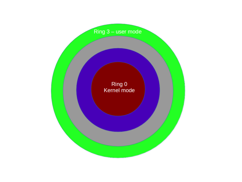
Rings

Some instructions can only be executed in ring 0. Examples are the instructions STI and CLI that start and stop interrupt processing (and potentially bring everything to a grinded halt as modern operating systems are interrupt driven, as we have seen in a previous post) or the command to reload the register CR3 which contains the base address of a page table directory and therefore the ability to load a new set of page tables. It is also possible to restrict the access to hardware using I/O ports to certain rings, so that code executing in user mode can, for instance, not directly access the hard drive or other devices.

Technically, the current ring is determined by the content of a special register called the code segment register (CS) – most likely an old friend of yours if you have ever written assembly code for the 8086, we get back to this point further below. As so often in the x86 architecture, this is an indirect mechanism. The CS contains a pointer into a table called the global descriptor table (GDT) which again holds the actual descriptions of the segments. Part of each entry is a two-bit field which specifies the ring. Thus if the CS points, say, at the third entry in the GDT and those two-bits in this entry contain 0b11, the CPU executes instructions at ring 3.

Switching the privilege level

Switching the privilege level requires a bit more work than just updating CS. The easiest way to force the CPU to pick up the new settings is to raise a software interrupt (technically, there is an alternative called a far jump that we will not discuss in detail). The beauty of this is that a piece of code executing in user mode can raise an interrupt to reach ring 0, but this interrupt will execute a well defined code, namely the interrupt service handler, which again can be set up only while being in ring 0. So at startup, the operating system – executing at ring 0 – can set up the interrupt service handler to point to specific routines in the kernel, and later, during normal operations, a program executing in user mode can at any time call into the kernel by raising a software interrupt, for instance in order to read from the hard drive. However, a user mode program can only execute the specified interrupt service handler and is not able to execute arbitrary code at ring 0. Thus user mode and kernel mode are separated, but the interrupt service handlers provide specific gates to switch forth and back.

To make this work, the operating system needs to let the CPU know where each interrupt service handler is located. In protected mode, this is the purpose of the interrupt descriptor table (IDT) which an operating system needs to prepare and which contains, for each of the theoretically possible 256 interrupt service handlers, the address of the interrupt service handler as well as additional information, for instance which code segment to use (which will typically point to ring 0 to execute the interrupt in kernel mode).

My toy operating system ctOS, for instance, uses the interrupt 0x80 for system calls. A program that wants to make a system call puts a number identifying the system call into a specific register (EAX) and then raises interrupt 0x80. The interrupt service handler evaluates EAX and branches into the respective system call handler, see the ctOS system call handler documentation for more details.

Interrupts can not only be used to switch from user mode to kernel mode, but also for the way back. In fact, whenever the CPU returns from an interrupt service handler, it will return to the ring at which the execution was interrupted, using the stack to bring back the CPU into its original state. In order to move from ring 0 to ring 3, we can therefore prepare a stack that looks like being the stack arranged by the CPU if an interrupt occurs, and then execute the IRET instruction to simulate returning from an interrupt service handler.

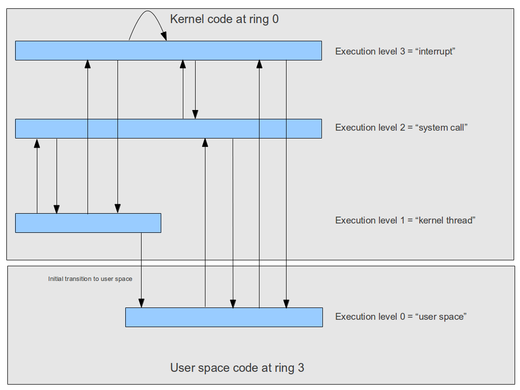
Matters get a bit more complicated by the fact that an interrupt service handler can in turn be interrupted by another interrupt, and that an operating system might want to implement kernel level threads which run outside of an interrupt context quite similar to a thread in user mode. To differentiate between those different situations, ctOS uses the concept of an execution level which is a software-maintained number describing the current context, as visualized below.
Memory model in protected mode

Another major change that the protected mode introduced into the x86 architecture was a more complex, but also more flexible memory model. To understand this, let us see how the older 8086 CPU handled memory (which is the mechanism that all modern Intel CPUs still use when being in real mode).

The 8086 was a 16-bit CPU, meaning that its registers were 16 bits wide. Therefore, a command like “put 0x10 into the memory location referenced by register AX” could only address 216=65536 different memory locations. To be able to address more memory, the Intel engineers therefore came up with a trick. When memory was accessed, the content of two registers was used. In the example above, this would be AX (16 bits) and the code segment register CS, which has 16 bits as well. To determine the actual memory location, the content of the CS register was shifted left by four bits and then added to the content of AX. Thus, if, for instance, AX contained 0x200 and CS contained 0x100, the address would be

(0x100 << 4) + 0x200 = 0x1000 + 0x200 = 0x1200

This addressing mode is sometimes called segmentation because we can think of it as dividing the memory space into (overlapping) segments of 64 kByte and the CS register as selecting one segment.

Using segmentation, the 8086 CPU could address a bit more than 1 MB of memory and thus work around the limitations of a 16 bit CPU. With a 32 bit CPU, this is not really needed any more, but the 80386 nevertheless expanded on this idea and came up with a bit more complicated model.

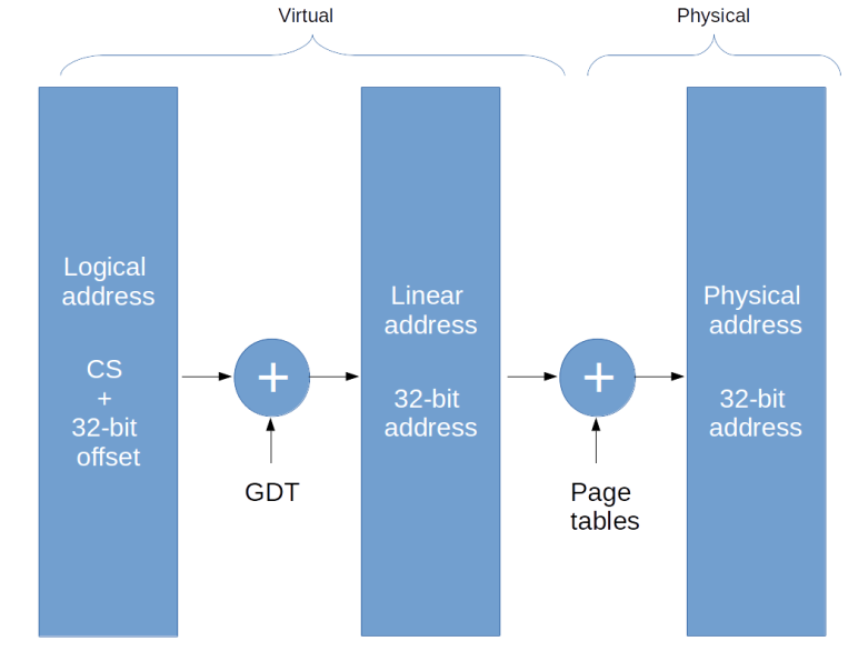
In fact, in protected mode, there are three different types of addresses which can be used to describe the location of a specific byte in memory.

The first type of address is the logical address. Similarly to real mode, a logical address consists of a segment selector (16 bit) which specifies the memory segment the byte is located in and an offset (32 bit) which specifies the location of the memory space within the segment.

A program running in user mode usually only sees the offset – this is what appears for instance if you dump the value of a pointer in a user mode C program. The segment selector is set by the operating system and usually not changed by a user mode program. So from the programs point of view, memory is entirely described by a 32 bit address and hence appears as a 4 GB virtual address space.

When accessing memory, the CPU uses the global descriptor table to convert this logical address into a linear address which is simply a 32 bit value. This is similar to real mode where the segment and offset are combined into a linear 20 bit wide address, with the difference that the base address of the segment is not directly taken from the CS register but the CS register only serves as pointer into the GDT that holds the actual base address.

Logical and linear address are still virtual addresses. To convert the linear address into a physical address, the CPU finally uses a page table directory and a page table as explained in one of my last posts. When the CPU has first been brought into protected mode, paging is still disabled, so this final translation step is skipped and linear and physical address are the same. Note, however, that the translation between logical and linear address cannot be turned off and is always active. So setting up this translation mechanism and in particular the GDT is one of the basis initialization step which needs to be done when switching to protected mode.
Addressing

Support for hardware multi-tasking

Apart from privilege levels and virtual memory, there is even more that the protected mode can do for you. In fact, the protected mode offers hardware support for multi-tasking.

Recall from my post on multi-tasking that a task switch essentially comes down to storing the content of all registers in a safe place and restoring them later. In the approach presented in my post, this is done by manually placing the registers on a stack. However, the x86 protected mode offers an alternative – the task state segment (TSS). This is an area of memory managed by the CPU that fully describes the state of a task. An operating system can initiate a task switch, and the CPU will do all the work to reload the CPU state from the TSS.

However, this mechanism is rarely used. It has a reputation of being slower than software task switching (though I have never seen any benchmarks on this), it introduces a lot of dependencies to the CPU and I am not aware of any modern operating system using this mechanism (Linux apparently used it in early versions of the kernel). Still, at least one TSS needs to be present in protected mode even if that mechanism is not used, as the TSS is also used to store some registers when an interrupt is raised while executing in ring 3 (see the corresponding section of the ctOS documentation for more details).

Long mode

Having followed me the long and dusty road down to an understanding of the protected mode, this one will shock you: protected mode is legacy.

In fact, the protected mode as we have discussed it is a 32 bit operating mode. Since a few years, however, almost every PC you can buy is equipped with a 64 bit CPU based on the x86-64 architecture. This architecture is fully backwards compatible, i.e. you can still run a protected mode operating system on such a PC. However, this does not allow you to address more than 4 GB of memory, as pointers are limited to 32 bit.

In long mode, the CPU uses 64 bit registers and is able to use 48 bit addressing, which is good enough for 256 TB of RAM.

Fortunately, if you understand the protected mode, getting used to long mode is not too difficult. The basis concepts of the various tables that we have discussed (page tables, the IDT and the GDT) remain unchanged, but of course the layout of these tables changes to accommodate for the additional address bits. The register set, however, changes considerably. The general purpose registers are extended to 64 bits and are renamed (RAX instead of EAX etc.). In addition, a few new registers become available. There are eight additional integer registers (R8 – R15) – which are typically used to pass arguments to subroutines instead of using the stack for this purpose – and eight more SSE registers.

Apart from that, long mode is just another mode of the x86 CPU family. And this is not the end of the story – there is unreal mode, there is virtual 8086 mode, there is the system management mode and there are new modes (“VMX root mode”) that support virtualization. If you want to learn more, I recommend the excellent OSDev Wiki – maybe the most valuable single OSDev site out there – and of course the Intel Software Developer manuals. Good luck!

Navigating downhill: the quantum variational eigensolver

In quantum mechanics, the dynamics of a system is determined by its Hamiltonian, which is a hermitian operator acting on the Hilbert space that describes the system at hand. The eigenstates and eigenvalues of the Hamiltonian then correspond to stationary states and their energies, and finding these eigenstates and the corresponding eigenvalues is the central task in computational quantum mechanics.

Unfortunately, in most cases, this is very hard. First, the Hilbert space of most physically relevant systems is infinite-dimensional. However, even if we are able to approximate the Hamiltonian by a hermitian operator acting on a finite dimensional subspace, finding the eigenvalues and eigenstates by applying classical methods from numerical linear algebra like the QR method is computationally challenging due to the high dimensional spaces involved. It is natural to ask whether a quantum computer can help.

In fact, there are several methods available for finding eigenvalues of a hermitian matrix on a quantum computer. In 1995, A. Kitaev described an algorithm which is now known as the quantum phase estimation (see [2] and [3]) which can be used to estimate eigenvalues of unitary matrices (and can be applied to hermitian matrices as well noting that if A is a hermitian matrix, U = eiAt is unitary and that there is an obvious relation between the eigenvalues of U and A). Unfortunately, this algorithm might require a large number (millions or even billions) of fault-tolerant quantum gates which is currently completely out of reach. This is the reason why a second algorithm which was first described in [1] and is designed to run on a quantum computer with a low number of qubits attracted a lot of attention. This algorithm, called the variational quantum eigensolver, might be able to deliver improvements over what is possible with classical hardware with somewhere between a few tens and one hundred qubits.

Setup and preliminaries

To explain the approach, let us assume that we are given a quantum register with n qubits and some hermitian operator H acting on the corresponding 2n-dimensional Hilbert space. We assume further that we can write our operator as a linear combination

H = \sum_i h_i H_i

of a small number of operators Hi which correspond to measurements that we can easily implement. An example could be a decomposition

H = \sum_i h_i P_i

where each Pi is a tensor product of Pauli matrices (it is not difficult to see that such a decomposition exists for every hermitian operator. First, write the operator as a linear combination of projections |x_i \rangle \langle x_i | and the vectors as linear combinations of tensor products to show that each hermitian operator is a linear combination of tensor products of hermitian single-qubit operators, and then use the fact that each hermitian single qubit operator is a linear combination of Pauli matrices). A tensor product of Pauli matrices corresponds to a measurement that can be easily implemented by a combination of a measurement in the standard computational basis and a unitary transformation, see for instance this discussion of Pauli measurements.

Now if the operators Hi correspond to measurements that can efficiently be implemented, it is also possible to efficiently evaluate the expectation value

\langle H_i \rangle = \frac{\langle \psi | H_i | \psi \rangle }{\langle \psi | \psi \rangle}

for a given state |\psi \rangle , assuming that we can efficiently prepare the state N times and then conduct N independent measurements – in fact, if N is sufficiently large, the expectation value will simply be the average over the measurements (see [4], section IV, for a more detailed discussion) – here we see a trade-off between the number of times we need to prepare the state |\psi \rangle and measure and the resulting precision.

Once we are able to measure the expectation value of each Hi, we can easily obtain the expectation value of H as the weighted average

\langle H \rangle = \sum h_i \langle H_i \rangle

A second observation that we need in order to understand the variational quantum eigensolver is the fact that the problem of finding the eigenvalues can be reduced to a variational problem. In fact, suppose that we are given a hermitian matrix A on a finite dimensional Hilbert space with eigenvalues \lambda_1, \lambda_2, \dots . Let us order the eigenvalues (which are of course real) such that \lambda_1 \leq \lambda_2 \leq \dots , and let us assume that |\psi_1 \rangle, |\psi_2 \rangle \dots is an orthonormal basis of corresponding eigenvectors.

If we are now given an arbitrary non-zero vector |\psi \rangle, we can of course expand this vector as a linear combination

|\psi \rangle = \sum_i a_i |\psi_i \rangle

which immediately gives us the following expression for the expectation value

\langle A \rangle = \frac{1}{\langle \psi | \psi \rangle} \sum_i |a_i|^2 \lambda_i

Given the ordering of the eigenvalues, we can now estimate this number as follows.

\langle A \rangle = \frac{1}{\langle \psi | \psi \rangle} \sum_i |a_i|^2 \lambda_i \geq \frac{1}{\langle \psi | \psi \rangle} \sum_i |a_i|^2 \lambda_1 = \lambda_1

It is also obvious that we have equality if |\psi \rangle is actually an eigenvector of A with eigenvalue \lambda_1 . Thus finding an eigenvector for the lowest eigenvalue of A is equivalent to minizing the expectation value of A!

This is at the heart of many variational methods like the Ritz method that have always been part of the toolset of computational quantum mechanics. In most of these methods, one considers state vectors parametrized by a finite dimensional parameter set, i.e. states of the form |\psi(\Theta) \rangle where the parameter \Theta ranges over some subset of a finite dimensional euclidian space. One then tries to minimize the expectation value

\langle H \rangle (\Theta) = \frac{\langle \psi(\Theta) | H | \psi(\Theta) \rangle}{\langle \psi(\Theta) | \psi(\Theta) \rangle}

using classical methods from mathematical optimization. The state vector minimizing this expectation value is then taken as an approximation for an eigenvector of H for its lowest eigenvalue.

Many classical optimiziation approaches that one might want to employ for this task work iteratively. We start with some value of the parameter \Theta, then determine the expectation value, adjust the parameter, determine the next expectation value and so forth. Unfortunately, calculating the expectation value of a matrix in a high dimensional Hilbert space is computationally very hard, which makes this algorithm difficult to apply to quantum systems with more than a few particles.

The algorithm

This is the point where the quantum variational eigensolver comes into play. If the operator H can – as assumed above – be decomposed into a sum of operators for which finding the expectation value can efficiently be done, then we can efficiently determine the expectation value of H as well and can use that in combination with a classical optimization algorithm to find an approximate eigenvector for H.

More precisely, here is the outline of the variational quantum eigensolver algorithm.

  1. Decompose the operator H as a linear combination H = \sum_\alpha h_\alpha H_\alpha where the expectation value of each H_\alpha can be efficiently determined
  2. Choose an initial value for the parameter \Theta
  3. Prepare the quantum computer in the state |\psi(\Theta) \rangle
  4. For each H_\alpha, use measurements to determine the expectation value \langle H_\alpha \rangle
  5. Calculate the expectation value of H as the weighted average \langle H \rangle = \sum_\alpha h_\alpha \langle H_\alpha \rangle
  6. Apply a classical optimization step to determine a new value for the parameter \Theta
  7. Start over with step 3 and repeat

So the algorithm switches forth and back between a quantum part – preparing the state and finding the expectation values – and a classical part, i.e. performing the actual optimization, and is therefore a prime example for a hybrid approach. This is visualized in the diagram below (which is a variation of the diagram presented in [1]).

VariationalQuantumEigensolver

Of course, to fully specify this algorithm, we have to define a method how to prepare the states efficiently and need to pick a classical optimization algorithm. In [1], the so-called coupled cluster method is chosen to prepare a state. In this method, the prepared state is given by applying a (parametrized) unitary transformation to a fixed reference state, and this unitary transformation can be efficiently implemented on a quantum computer. As an optimization algorithm, the downhill simplex method, also known as the Nelder-Mead method, is employed.

As noted in [1], the algorithm makes a certain trade-off between the number of iterations required to estimate the expectation values and perform the optimization step and the time required to run a single iteration on the quantum device. One of the main problems that todays quantum computers face, however, is to keep a quantum state stable over a longer period of time. Therefore the bottleneck is the run time or the number of operations that we spend in the quantum part of the algorithm, which this approach tries to minimize. As explained in [4], the variational principle also remains valid if we consider quantum systems with noise, which is an indication that the algorithm is comparatively resistant to noise. All this makes the quantum variational eigensolver a good candidate for a true quantum advantage on a near-term, noisy and not fully fault-tolerant quantum device.

Applications in computational chemistry

So far we have implicitly dealt with Hamiltonians H on a Hilbert space representing a quantum register, i.e. a tensor product of one qubit systems. For applications, there is therefore one additional step that we need to carry out in order to be able to apply the algorithm – we need to map the system and the Hamiltonian in question to an n-qubit quantum system. This involves in particular a projection of the (typically) infinite dimensional Hilbert space of the original problem onto a finite dimensional system.

A prime example that is detailed in [4] and in [1] is the Hamiltonian describing an atom with N electrons and their interactions with the nucleus and other electrons. Finding the eigenstates and eigenvalues of this Hamiltonian is known as the electronic structure problem.

In general, this is a difficult problem. Of course, the easiest case of this – the hydrogen atom – can be solved analytically and is treated in most beginner courses in quantum mechanics. However, already for the Helium atom, no closed solution is known and approximations have to be used.

In order to apply the variational quantum eigensolver to this problem, a mapping to a Hilbert space describing a quantum register needs to be done. As explained in [1], this can be done using the mechanism of second quantization and the Jordan-Wigner transform. In this paper, the authors have applied the method to estimate the strength of the chemical bond in a helium hydride ion HeH+, which is formed by the reaction of a proton with a helium atom. They show that in order to obtain a very good approximation, a four-dimensional Hilbert space is sufficient, so that the algorithm can be carried out on a quantum computer with only two qubits. Recently ([5]), this has been extended to a six-qubit system used to estimate the ground state energy of a BeH2 molecule. Of course these are still comparatively small systems, but these experimental results encourage the hope that the approach scales and can be used on medium scale near-term quantum devices to go beyond what is possible with classical computers.

This work is also described in a post on the IBM website. IBM has made the Python sourcecode for similar applications available as part of its QISKit quantum computation library, so that everybody with a Q Experience account can run the algorithm and play with it. QISKit is a very interesting piece of software, and I will most likely devote one or more future posts on QISKit and similar frameworks like pyQUIL.

References

1. A. Peruzzo et. al., A variational eigenvalue solver on a photonic quantum processor, Nature Communications volume 5 (2014), available at www.nature.com/articles/ncomms5213
2. A. Kitaev, Quantum measurements and the Abelian Stabilizer Problem, arXiv:quant-ph/9511026
3. R. Cleve, A. Ekert, C. Macchiavello, M. Mosca, Quantum Algorithms Revisited, arXiv:quant-ph/9708016
4. J. R. McClean, J. Romero, R. Babbush, A. Aspuru-Guzik, The theory of variational hybrid quantum-classical algorithms, arXiv:1509.04279
5. A. Kandala, A. Mezzacapo, K. Temme,
M. Takita, M. Brink, J. M. Chow, J. M. Gambetta, Hardware-efficient Variational Quantum Eigensolver for Small Molecules and Quantum Magnets, Nature volume 549, pages 242–246 (14 September 2017), available as arXiv:1704.05018v2

Into the quantum lab – first steps with IBMs Q experience

Even though physical implementations of quantum computers make considerable progress, it is not likely that you will have one of them under your desk in the next couple of years. Fortunately, some firms like IBM and Rigetti have decided to make some of their quantum devices available only so that you can play with them. In this post, we will have a first look at IBMs cloud offering – the IBM Q experience.

IBM offers different ways to interact with their quantum computers. The easiest access is provided by the interactive composer which allows you to create a quantum circuit online and to run it on a 5 qubit quantum computer based on superconducting qubits after registering.

The screenshot below shows the editor screen. At the top, you find an overview of the available quantum devices, both realising five (physical) qubits, and some of the main characteristics like error rates and decoherence times.

IBMQExperience_EditorScreen

In the lower area of the screen, you can compose quantum circuits graphically. You can add quantum gates that manipulate the five qubits q[0] – q[4] and measurements. After setting up your circuit, you can either simulate the circuit or you can run it on the actual device. It is also possible to export the circuit as a QASM code snippet and to save experiments and results as so-called quantum scores.

Let us now run this circuit on the actual quantum hardware. Doing this consumes units, i.e. credits. A standard run consists of 1024 repetitions and one measurement after each repetition and consumes three units (which are replenished after the execution has completed). The execution is queued and, typically after a few minutes, the results are made available online (and you receive a mail informing you about the execution). When running a circuit, the platform also checks whether that circuit was executed before (by you our someone else) and if yes offers you immediate access to the previous results without consuming any units. The screenshot below shows the result of one of these runs.

IBMQExperience_SampleResult

The interesting part is the diagram at the top that shows the measurement outcomes in the computational basis, i.e. for each member of the computational basis on the x-axis, the value shows the percentage of measurements having that basis element as result. In this example, we see that almost always, the result is 00000, as expected from the circuit in which we do a double inversion of the first qubit. However, in some cases – corresponding to 1,3 percent of all runs – the outcome is 00001. This is a nice example for an error that occurs whenever we switch from a simulator to a real physical device. Note that in the IBM Q experience, the qubit q[0] is the least significant qubit and the rightmost qubit in the notation of the computational basis.

Now let us try something else – we want to put our system into an equal superposition

\sum_i |i \rangle

which is the usual starting point for most quantum algorithms. We know that we can achieve this by applying a Hadamard gate on each qubit. The following screenshot shows the resulting circuit for three qubits and the results of a (cached) run.

 ibmqexperience_hadamard.png

As expected, we see that our measurement results are spread across eight (23) vectors of the computational basis. However, we also see that again, the result does not exactly match the theoretical prediction – the values are not exactly equally distributed but we see slight deviations as before.

Finally, let us try out a multi-qubit gate. The screenshot below shows the result of a run with two CNOT gates. The first CNOT gate receives a logical one on its control bit, the second CNOT gate a logical zero. Thus, the result should be 00011, i.e. the first (least significant) qubits are inverted. In reality, we again get this result plus some noise, represented by unexpected outcomes in the measurements.

ibmqexperience_cnot.png

Playing with the composer is fun, and makes it easy to create simple circuits from scratch. However, more complicated circuits soon become difficult to define in this way. For those circuits, the IBM platform offers an API that can be used to run experiments using Python scripts that can much easier be developed and debugged step by step. We will look at this option in a later post. Until then, I recommend you get an account and create some circuits yourself – happy hacking!

Virtual memory

If you wanted a slogan that summarizes key trends in the IT industry over the last 30+ years, then “everything is virtual” would be a good candidate. In todays computing environments, essentially every physical resource is virtualized – and pretty much the first resource where this happened in mainstream computing was memory. In this post, we will look a bit into virtual memory: what it is, how it is implemented and how it is used.

To introduce the concept, suppose you were running a document storage service. Maybe you own a large warehouse with thousands of little boxes, and customers can hand in envelopes with documents that you will then safely store in one of the boxes. Obviously, you need a smart way to manage all these little envelops and boxes.

The first approach that someone might come up with is very simple. Suppose that your warehouse contains 10.000 boxes and each box can store one envelope. You could then number the boxes, say from zero to 9.999, and ask customers to label their envelops with numbers in that range. When a customer hands in an envelope that has, say, 11 on it, then an agent accepts the envelope and simply puts it into the box that has exactly that number, i.e. 11 in this case.

PhysicalMemory

In the world of computing, this is how physical memory addresses work. Of course, the agent corresponds the memory controller and the customer to the CPU. When the CPU wants to store some data in memory, it passes that data (the envelope) along with the address where the data should be stored to the memory controller, and the memory controller stores the data at the requested address.

That model is simple, and the first customer will love it – the customer can freely decide about where the envelope should be placed, and feels like owning the entire warehouse exclusively.

However, suppose you are the second customer. If, for some reason, you also want to store an envelope in box 11, there is a problem as this box is already taken. Similar problems are caused by physical memory addressing if you want to implement multitasking, i.e. allow several programs (customers) to use resources of the PC (i.e. memory) simultaneously. If, for instance, you want to run two programs that are both designed to start at address 0x100 in memory, the first program will properly load and execute, but it will consume this area of memory and you will not be able to load and run the second program. This is the mode that most early CPUs used, for instance the 8086 used in the first IBM PCs (and todays CPUs still start in the so-called real mode that uses the same addressing pattern with a bit of a twist).

So for multitasking, you need a different model. Let us look at our warehouse again. Instead of just storing the envelope in the box designated by the label on the envelope, the agent could, for each and every customer, maintain a mapping table. When a customer hands in an envelope, say again with label 11, the agent would locate an unused box. This can have any label, say it is 3. The agent would then add an entry to the mapping table that maps – for this customer – label 11 to box 3, and store the envelope in box 3. If a second customer also hands in an envelope with label 11, the agent would add a similar entry to the mapping table for this customer, this time mapping 11 to – say – box 7

Similarly, if a customer requests to retrieve an envelope, say again envelope 11, the agent would consult the mapping table for this specific customer and see that the envelope is located in box 3, so that it can be located and handed over to the customer. The agent could then either mark the box as unused again or agree with the customer to reserve the space for later use.

VirtualMemory

Of course, this requires some overhead – the agent needs to maintain mapping tables, one table per customer. But assuming that there is still enough space left in the warehouse, every customer still feels like owning the entire warehouse – in fact, the customer is not even able to detect a difference to the first system. And there are more interesting opportunities that the system offers. If, for instance, a new customer arrives but the warehouse is full, the agent could locate a box that has not been used for a while, transfer the content of this box into some other storage room and use the box again.

Translated back to the world of computing, this model corresponds to virtual memory addresses. In that model, an additional translation unit sits between the CPU and the memory controller. This unit uses a system of mapping tables – called the page tables – to map forth and back between virtual and physical addresses. An operating system implements one different set of tables, i.e. a different mapping, for each process. Thus each process is like the customer in our warehouse example and logically can access the entire virtual memory space, even if other processes run at the same time. The operating system can even swap out areas of memory, i.e. if physical memory is exhausted, it could copy parts of its content onto a slower medium, say the hard drive, and reallocate that space – a mechanism which is usually called swapping.

There is much more that we can do having virtual memory at our disposal. We could, for instance, implement a mechanism called copy-on-write. Suppose that you wanted to copy a large area of physical memory which can be quite time consuming. Instead of copying, you could simply adapt the address mapping such that different virtual addresses point to the same physical address. For the CPU, which only sees virtual addresses, it appears like if the content had copied – until, of course, the CPU tries to change the copy. So the operating system needs to listen for writes into this memory area, and only if that write takes place create an actual physical copy. If we are lucky, only a comparatively small area of the copied memory is actually written to, and then copy-on-write can be much more efficient in terms of performance and overall memory utilization than a plain physical copy.

Designing the structure of the mapping tables requires some care. Of course, we cannot map every single byte of memory – storing that mapping information alone would consume the entire system memory. Instead, the memory is divided into small chunks called pages. Traditionally, a page is 4096 bytes, but other page sizes are feasible. We then map page by page, i.e. for each page, we map its starting address in virtual address space to a corresponding physical page.

In fact, this mapping is usually organized as a hierarchy of page tables, with the lowest level being the so-called page table directory. Each page table has 1024 entries, each of which describes the mapping of one page, so each page table is able to hold the mapping for 4 MB of memory. Thus we need 1024 page tables to describe the full address space accessible with 32 bits. The page table directory is then another table that simply holds the address of these 1024 page tables, as illustrated below.

PageTables

In practice, there is not only one page table directory, but several page table directories, such that each process uses a different set of page table and hence a different mapping of physical and virtual addresses, i.e. a different virtual address space. In fact, for most operating systems, a process and an address space are almost synonyms. For Unix like operating systems, each process has a separate address space, but all threads running within this process share this address space which is an important conceptual difference between threads and processes.

To be able to use several page table directories, we need a way to switch between them. On the x86 platform, this is done by loading the address of the page table directory into a special register of the CPU called CR3. When we switch forth and back between two threads or tasks that do not belong to the same process, the operating system needs to make sure that the register CR3 is loaded with the address of the new page table directory corresponding to the process to which we switch. As every process has its own virtual-to-physical address mapping, the address spaces of two different processes are very effectively isolated and we can make sure that process A does not read or write memory allocated by process B and vice versa.

There is one problem, though. Changing the value of CR3 is, at the end of the day, an ordinary instruction. If every process could execute this instruction, a process could reload CR3 with a pointer to a manipulated page table. Thus, every process would be able to change the mapping between virtual and physical memory, effectively destroying the isolation.

The solution is to introduce privilege levels. Each process is running at one of these levels, and the operating system is running at the highest level. We could then make the instructions that manipulate CR3 privileged instructions that only the operating system is allowed to execute, and thus only the operating system could change page tables. These different privilege levels have been introduced into the x86 architecture as part of the protected mode that is also required to implement virtual memory and which will be the topic of one of the next posts in this series.