The protected mode in the x86 architecture

Modern operating systems would not be possible without the ability of a CPU to execute code at different privilege levels. This feature became available for mainstream PCs in the early eighties, when Intel introduced its 80286 and 80386 CPUs, and was readily employed by operating systems like Windows 3.11 and, of course, Linux, which Linus Torvalds once called “a project to teach me about the 386”.

When an 80286 or 80386 CPU (and all later models) is starting up, it is initially operating in what is called real mode, and behaves like the earlier 8086 which is the CPU used by the famous IBM PC XT. To enjoy the benefits of protected mode, the operating system has to initialize a few system tables and can then switch to protected mode. It is also possible, though a bit harder, to switch back to real mode – and some operating systems actually do this in order to utilize functions of the legacy BIOS which is designed to be called from real mode.

One of the features that the protected mode offers is virtual memory and paging, a technology that we have already discussed in a previous post. In addition, and maybe even more important, the protected mode allows code to be execute in one of four privilege levels that are traditionally called rings.

Privilege levels

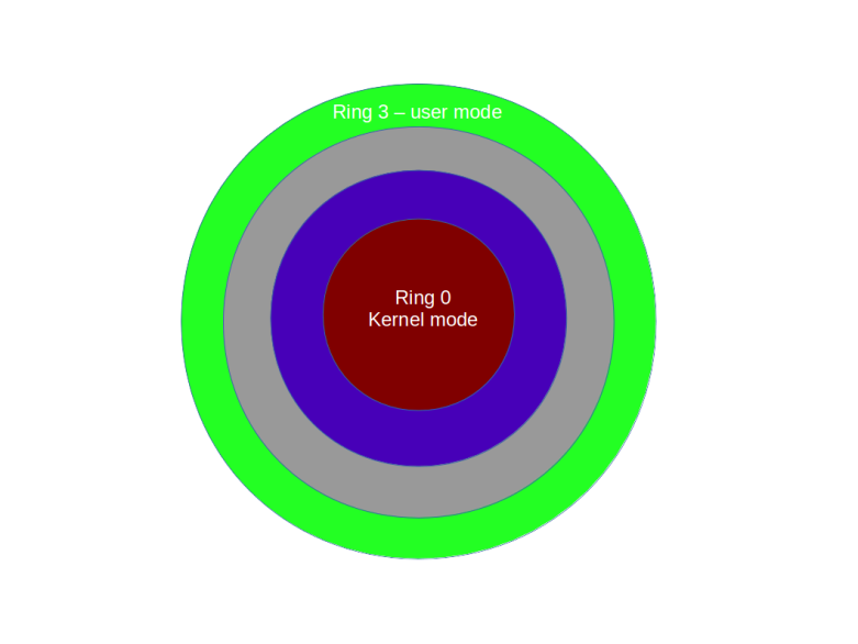
At any point in time, the CPU executes code at one of four ring (ring 0 to ring 3). The current ring determines which instructions are allowed and which instructions are forbidden, with ring 0 – sometimes called kernel mode or supervisor mode – being the most privileged level, and ring 3 – typically called user mode – being the lowest privilege level.
Rings

Some instructions can only be executed in ring 0. Examples are the instructions STI and CLI that start and stop interrupt processing (and potentially bring everything to a grinded halt as modern operating systems are interrupt driven, as we have seen in a previous post) or the command to reload the register CR3 which contains the base address of a page table directory and therefore the ability to load a new set of page tables. It is also possible to restrict the access to hardware using I/O ports to certain rings, so that code executing in user mode can, for instance, not directly access the hard drive or other devices.

Technically, the current ring is determined by the content of a special register called the code segment register (CS) – most likely an old friend of yours if you have ever written assembly code for the 8086, we get back to this point further below. As so often in the x86 architecture, this is an indirect mechanism. The CS contains a pointer into a table called the global descriptor table (GDT) which again holds the actual descriptions of the segments. Part of each entry is a two-bit field which specifies the ring. Thus if the CS points, say, at the third entry in the GDT and those two-bits in this entry contain 0b11, the CPU executes instructions at ring 3.

Switching the privilege level

Switching the privilege level requires a bit more work than just updating CS. The easiest way to force the CPU to pick up the new settings is to raise a software interrupt (technically, there is an alternative called a far jump that we will not discuss in detail). The beauty of this is that a piece of code executing in user mode can raise an interrupt to reach ring 0, but this interrupt will execute a well defined code, namely the interrupt service handler, which again can be set up only while being in ring 0. So at startup, the operating system – executing at ring 0 – can set up the interrupt service handler to point to specific routines in the kernel, and later, during normal operations, a program executing in user mode can at any time call into the kernel by raising a software interrupt, for instance in order to read from the hard drive. However, a user mode program can only execute the specified interrupt service handler and is not able to execute arbitrary code at ring 0. Thus user mode and kernel mode are separated, but the interrupt service handlers provide specific gates to switch forth and back.

To make this work, the operating system needs to let the CPU know where each interrupt service handler is located. In protected mode, this is the purpose of the interrupt descriptor table (IDT) which an operating system needs to prepare and which contains, for each of the theoretically possible 256 interrupt service handlers, the address of the interrupt service handler as well as additional information, for instance which code segment to use (which will typically point to ring 0 to execute the interrupt in kernel mode).

My toy operating system ctOS, for instance, uses the interrupt 0x80 for system calls. A program that wants to make a system call puts a number identifying the system call into a specific register (EAX) and then raises interrupt 0x80. The interrupt service handler evaluates EAX and branches into the respective system call handler, see the ctOS system call handler documentation for more details.

Interrupts can not only be used to switch from user mode to kernel mode, but also for the way back. In fact, whenever the CPU returns from an interrupt service handler, it will return to the ring at which the execution was interrupted, using the stack to bring back the CPU into its original state. In order to move from ring 0 to ring 3, we can therefore prepare a stack that looks like being the stack arranged by the CPU if an interrupt occurs, and then execute the IRET instruction to simulate returning from an interrupt service handler.

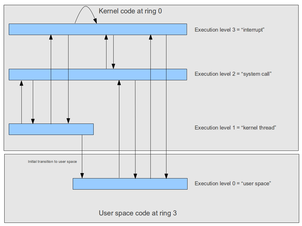
Matters get a bit more complicated by the fact that an interrupt service handler can in turn be interrupted by another interrupt, and that an operating system might want to implement kernel level threads which run outside of an interrupt context quite similar to a thread in user mode. To differentiate between those different situations, ctOS uses the concept of an execution level which is a software-maintained number describing the current context, as visualized below.
Memory model in protected mode

Another major change that the protected mode introduced into the x86 architecture was a more complex, but also more flexible memory model. To understand this, let us see how the older 8086 CPU handled memory (which is the mechanism that all modern Intel CPUs still use when being in real mode).

The 8086 was a 16-bit CPU, meaning that its registers were 16 bits wide. Therefore, a command like “put 0x10 into the memory location referenced by register AX” could only address 216=65536 different memory locations. To be able to address more memory, the Intel engineers therefore came up with a trick. When memory was accessed, the content of two registers was used. In the example above, this would be AX (16 bits) and the code segment register CS, which has 16 bits as well. To determine the actual memory location, the content of the CS register was shifted left by four bits and then added to the content of AX. Thus, if, for instance, AX contained 0x200 and CS contained 0x100, the address would be

(0x100 << 4) + 0x200 = 0x1000 + 0x200 = 0x1200

This addressing mode is sometimes called segmentation because we can think of it as dividing the memory space into (overlapping) segments of 64 kByte and the CS register as selecting one segment.

Using segmentation, the 8086 CPU could address a bit more than 1 MB of memory and thus work around the limitations of a 16 bit CPU. With a 32 bit CPU, this is not really needed any more, but the 80386 nevertheless expanded on this idea and came up with a bit more complicated model.

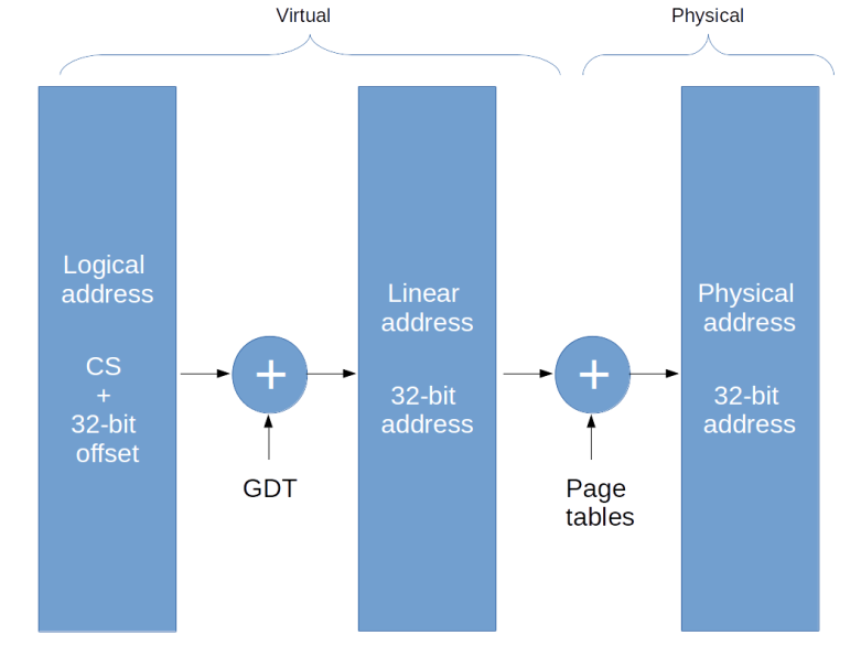
In fact, in protected mode, there are three different types of addresses which can be used to describe the location of a specific byte in memory.

The first type of address is the logical address. Similarly to real mode, a logical address consists of a segment selector (16 bit) which specifies the memory segment the byte is located in and an offset (32 bit) which specifies the location of the memory space within the segment.

A program running in user mode usually only sees the offset – this is what appears for instance if you dump the value of a pointer in a user mode C program. The segment selector is set by the operating system and usually not changed by a user mode program. So from the programs point of view, memory is entirely described by a 32 bit address and hence appears as a 4 GB virtual address space.

When accessing memory, the CPU uses the global descriptor table to convert this logical address into a linear address which is simply a 32 bit value. This is similar to real mode where the segment and offset are combined into a linear 20 bit wide address, with the difference that the base address of the segment is not directly taken from the CS register but the CS register only serves as pointer into the GDT that holds the actual base address.

Logical and linear address are still virtual addresses. To convert the linear address into a physical address, the CPU finally uses a page table directory and a page table as explained in one of my last posts. When the CPU has first been brought into protected mode, paging is still disabled, so this final translation step is skipped and linear and physical address are the same. Note, however, that the translation between logical and linear address cannot be turned off and is always active. So setting up this translation mechanism and in particular the GDT is one of the basis initialization step which needs to be done when switching to protected mode.
Addressing

Support for hardware multi-tasking

Apart from privilege levels and virtual memory, there is even more that the protected mode can do for you. In fact, the protected mode offers hardware support for multi-tasking.

Recall from my post on multi-tasking that a task switch essentially comes down to storing the content of all registers in a safe place and restoring them later. In the approach presented in my post, this is done by manually placing the registers on a stack. However, the x86 protected mode offers an alternative – the task state segment (TSS). This is an area of memory managed by the CPU that fully describes the state of a task. An operating system can initiate a task switch, and the CPU will do all the work to reload the CPU state from the TSS.

However, this mechanism is rarely used. It has a reputation of being slower than software task switching (though I have never seen any benchmarks on this), it introduces a lot of dependencies to the CPU and I am not aware of any modern operating system using this mechanism (Linux apparently used it in early versions of the kernel). Still, at least one TSS needs to be present in protected mode even if that mechanism is not used, as the TSS is also used to store some registers when an interrupt is raised while executing in ring 3 (see the corresponding section of the ctOS documentation for more details).

Long mode

Having followed me the long and dusty road down to an understanding of the protected mode, this one will shock you: protected mode is legacy.

In fact, the protected mode as we have discussed it is a 32 bit operating mode. Since a few years, however, almost every PC you can buy is equipped with a 64 bit CPU based on the x86-64 architecture. This architecture is fully backwards compatible, i.e. you can still run a protected mode operating system on such a PC. However, this does not allow you to address more than 4 GB of memory, as pointers are limited to 32 bit.

In long mode, the CPU uses 64 bit registers and is able to use 48 bit addressing, which is good enough for 256 TB of RAM.

Fortunately, if you understand the protected mode, getting used to long mode is not too difficult. The basis concepts of the various tables that we have discussed (page tables, the IDT and the GDT) remain unchanged, but of course the layout of these tables changes to accommodate for the additional address bits. The register set, however, changes considerably. The general purpose registers are extended to 64 bits and are renamed (RAX instead of EAX etc.). In addition, a few new registers become available. There are eight additional integer registers (R8 – R15) – which are typically used to pass arguments to subroutines instead of using the stack for this purpose – and eight more SSE registers.

Apart from that, long mode is just another mode of the x86 CPU family. And this is not the end of the story – there is unreal mode, there is virtual 8086 mode, there is the system management mode and there are new modes (“VMX root mode”) that support virtualization. If you want to learn more, I recommend the excellent OSDev Wiki – maybe the most valuable single OSDev site out there – and of course the Intel Software Developer manuals. Good luck!

Virtual memory

If you wanted a slogan that summarizes key trends in the IT industry over the last 30+ years, then “everything is virtual” would be a good candidate. In todays computing environments, essentially every physical resource is virtualized – and pretty much the first resource where this happened in mainstream computing was memory. In this post, we will look a bit into virtual memory: what it is, how it is implemented and how it is used.

To introduce the concept, suppose you were running a document storage service. Maybe you own a large warehouse with thousands of little boxes, and customers can hand in envelopes with documents that you will then safely store in one of the boxes. Obviously, you need a smart way to manage all these little envelops and boxes.

The first approach that someone might come up with is very simple. Suppose that your warehouse contains 10.000 boxes and each box can store one envelope. You could then number the boxes, say from zero to 9.999, and ask customers to label their envelops with numbers in that range. When a customer hands in an envelope that has, say, 11 on it, then an agent accepts the envelope and simply puts it into the box that has exactly that number, i.e. 11 in this case.

PhysicalMemory

In the world of computing, this is how physical memory addresses work. Of course, the agent corresponds the memory controller and the customer to the CPU. When the CPU wants to store some data in memory, it passes that data (the envelope) along with the address where the data should be stored to the memory controller, and the memory controller stores the data at the requested address.

That model is simple, and the first customer will love it – the customer can freely decide about where the envelope should be placed, and feels like owning the entire warehouse exclusively.

However, suppose you are the second customer. If, for some reason, you also want to store an envelope in box 11, there is a problem as this box is already taken. Similar problems are caused by physical memory addressing if you want to implement multitasking, i.e. allow several programs (customers) to use resources of the PC (i.e. memory) simultaneously. If, for instance, you want to run two programs that are both designed to start at address 0x100 in memory, the first program will properly load and execute, but it will consume this area of memory and you will not be able to load and run the second program. This is the mode that most early CPUs used, for instance the 8086 used in the first IBM PCs (and todays CPUs still start in the so-called real mode that uses the same addressing pattern with a bit of a twist).

So for multitasking, you need a different model. Let us look at our warehouse again. Instead of just storing the envelope in the box designated by the label on the envelope, the agent could, for each and every customer, maintain a mapping table. When a customer hands in an envelope, say again with label 11, the agent would locate an unused box. This can have any label, say it is 3. The agent would then add an entry to the mapping table that maps – for this customer – label 11 to box 3, and store the envelope in box 3. If a second customer also hands in an envelope with label 11, the agent would add a similar entry to the mapping table for this customer, this time mapping 11 to – say – box 7

Similarly, if a customer requests to retrieve an envelope, say again envelope 11, the agent would consult the mapping table for this specific customer and see that the envelope is located in box 3, so that it can be located and handed over to the customer. The agent could then either mark the box as unused again or agree with the customer to reserve the space for later use.

VirtualMemory

Of course, this requires some overhead – the agent needs to maintain mapping tables, one table per customer. But assuming that there is still enough space left in the warehouse, every customer still feels like owning the entire warehouse – in fact, the customer is not even able to detect a difference to the first system. And there are more interesting opportunities that the system offers. If, for instance, a new customer arrives but the warehouse is full, the agent could locate a box that has not been used for a while, transfer the content of this box into some other storage room and use the box again.

Translated back to the world of computing, this model corresponds to virtual memory addresses. In that model, an additional translation unit sits between the CPU and the memory controller. This unit uses a system of mapping tables – called the page tables – to map forth and back between virtual and physical addresses. An operating system implements one different set of tables, i.e. a different mapping, for each process. Thus each process is like the customer in our warehouse example and logically can access the entire virtual memory space, even if other processes run at the same time. The operating system can even swap out areas of memory, i.e. if physical memory is exhausted, it could copy parts of its content onto a slower medium, say the hard drive, and reallocate that space – a mechanism which is usually called swapping.

There is much more that we can do having virtual memory at our disposal. We could, for instance, implement a mechanism called copy-on-write. Suppose that you wanted to copy a large area of physical memory which can be quite time consuming. Instead of copying, you could simply adapt the address mapping such that different virtual addresses point to the same physical address. For the CPU, which only sees virtual addresses, it appears like if the content had copied – until, of course, the CPU tries to change the copy. So the operating system needs to listen for writes into this memory area, and only if that write takes place create an actual physical copy. If we are lucky, only a comparatively small area of the copied memory is actually written to, and then copy-on-write can be much more efficient in terms of performance and overall memory utilization than a plain physical copy.

Designing the structure of the mapping tables requires some care. Of course, we cannot map every single byte of memory – storing that mapping information alone would consume the entire system memory. Instead, the memory is divided into small chunks called pages. Traditionally, a page is 4096 bytes, but other page sizes are feasible. We then map page by page, i.e. for each page, we map its starting address in virtual address space to a corresponding physical page.

In fact, this mapping is usually organized as a hierarchy of page tables, with the lowest level being the so-called page table directory. Each page table has 1024 entries, each of which describes the mapping of one page, so each page table is able to hold the mapping for 4 MB of memory. Thus we need 1024 page tables to describe the full address space accessible with 32 bits. The page table directory is then another table that simply holds the address of these 1024 page tables, as illustrated below.

PageTables

In practice, there is not only one page table directory, but several page table directories, such that each process uses a different set of page table and hence a different mapping of physical and virtual addresses, i.e. a different virtual address space. In fact, for most operating systems, a process and an address space are almost synonyms. For Unix like operating systems, each process has a separate address space, but all threads running within this process share this address space which is an important conceptual difference between threads and processes.

To be able to use several page table directories, we need a way to switch between them. On the x86 platform, this is done by loading the address of the page table directory into a special register of the CPU called CR3. When we switch forth and back between two threads or tasks that do not belong to the same process, the operating system needs to make sure that the register CR3 is loaded with the address of the new page table directory corresponding to the process to which we switch. As every process has its own virtual-to-physical address mapping, the address spaces of two different processes are very effectively isolated and we can make sure that process A does not read or write memory allocated by process B and vice versa.

There is one problem, though. Changing the value of CR3 is, at the end of the day, an ordinary instruction. If every process could execute this instruction, a process could reload CR3 with a pointer to a manipulated page table. Thus, every process would be able to change the mapping between virtual and physical memory, effectively destroying the isolation.

The solution is to introduce privilege levels. Each process is running at one of these levels, and the operating system is running at the highest level. We could then make the instructions that manipulate CR3 privileged instructions that only the operating system is allowed to execute, and thus only the operating system could change page tables. These different privilege levels have been introduced into the x86 architecture as part of the protected mode that is also required to implement virtual memory and which will be the topic of one of the next posts in this series.

How does multitasking really work?

The first PC on which I was running a copy of Linux back in the nineties did of course only have one CPU, so it was clear to me that it could physically only execute one instruction at a time – but still, it magically created the impression to run several programs in parallel without visible delay. How could that ever work? Almost twenty years later, I finally found the answer.

In fact, trying to understand how multitasking and multithreading actually work was one of my main motivations when I developed the ctOS kernel a couple of years ago. In this post, I will try to explain the basic mechanism behind the magic.

The basic idea sounds simple enough. Suppose a task has been running for some time and the operating system decides that it is time to switch to a different task. Then the operating system kernel will interrupt the current execution and save the current state of the CPU somewhere in memory. It then locates a different task that is ready to be run – a process which is called scheduling– and retrieves the saved CPU state representing this task from memory. Then, it will let the CPU continue execution with that saved state. As this state is exactly the state of the CPU that was in place when the newly scheduled task was stopped, the CPU will continue to process this task as if it had never been interrupted.

Unfortunately, this simple explanation leaves a number of questions open. First, if a task is executing, it means that the CPU is busy running this task. How, then, can the operating system “do” something? Second, what is the “state of the CPU”? How can we store it and how can we put the CPU back in a saved state? And then, how do we decide that “it is time to switch to a different task”? It turns out that the answer to these questions have to do with interrupts.

Task switching, interrupts and the stack

To explain this, let us for a moment assume a vastly simplified world where all tasks currently active do not require I/O operations. Suppose task A is currently being processed, i.e. the CPU is executing the stream of instructions (the “program”) that make up this task. At some point, we will see an interrupt firing. If there is no I/O, this is usually the timer interrupt that fires periodically, say one thousand times per second.

If this happens, the CPU will stop the execution of task A and start to execute an interrupt service handler. Now the interrupt service handler has been set up by the operating system and points at code within the operating system kernel – so at this point, control is given to the operating system! At the same time, we have learned that the CPU will store the value of some registers like EIP on the stack, and a smart interrupt handler will store the value of additional registers on the stack as well in order to be able to use and reconstruct their value later, and, right at its end, contain code to pop the register values off the stack again. So we could as well set up our ISR in such a way that it does in fact store the value of all registers on the stack. This already provides two ingredients for the task switching mechanism – a way to make sure that the operating system gains control of the CPU at least once a millisecond and a saved CPU state on the stack!

Now the operating system will usually maintain a list of tasks and scan that list according to certain criteria to find a task which should be executed next – we will look at this process in greater detail further below. Suppose that it determines a task which we call B which should be run next. For the sake of simplicity, let us also assume that this task is not entirely new, but has already been running for some time (setting up a new task is a bit more complicated). Thus, when task B was interrupted for the last time, its state was also saved on the stack somewhere, and our operating system has hopefully stored a pointer to this stack.

What we now want to do is to exchange the stored state of task A with that of B. The easiest way to do this is not to copy around the stacks, but to manipulate the stack pointer such that the execution resumes using the stack of task B instead of task A! When we do this and reach the end of the interrupt service handler, the part of the interrupt service handler that is responsible for popping all registers off the stack again as well as the final IRET will use the stack of task B. In other words, the CPU will pick up the state of task B instead the state of task A. It will therefore continue execution with the state of the registers and the instruction pointer that task B had when it was interrupted – in other words, task B will continue to execute instead of task A, and we have switched from task A to task B.

TaskSwitch

In reality, there are a few subtle points that need to be worked out in more detail when you really want to build this. You will have to think about what the stack actually is – does every task have its own stack, how do you isolate them etc. In addition, a task switch might invoke a switch to a different process and thus to a different virtual address space, so at some point, addresses become invalid and cannot be accessed any more. The exact process that ctOS uses is described in the section on task switching in the interrupt handling documentation of ctOS.

We have explained the process of task switching using the timer interrupt as an example. However, this is not the only possible trigger for a task switch. There are of course other hardware interrupts that might trigger a task switch, but more importantly, many task switches do in fact occur during a system call! Assume for instance that a task wants to read data from the hard drive. It will then invoke a system call to do this, i.e. it will hand over control to the kernel voluntarily. The kernel will ask the hard drive to go and get the data, but of course this takes some time. Thus the kernel will in general not return to this task, but schedule a different task and execute a task switch. If (as ctOS does it) a system call is itself implemented as a software interrupt, the mechanism is exactly the same as if a task switch had been done during the processing of a hardware interrupt (if the faster SYSENTER/SYSEXIT mechanism is used, the processing is a bit different but the idea is the same).

Scheduling

What we have not explained so far is how the operating system does actually select a new task to be executed. The exact details how to do this are different for each operating system, but it is probably fair to say that there are in general two main ingredients – the time the task has been running until the last task switch and the state of the task.

First, there is the CPU time that a task has consumed since the last task switch, commonly measured by the quantum. The quantum is a number that is set to some initial value when the task gets control of the CPU. During each processing of the timer interrupt, the quantum of the currently active task is decreased by one. As the timer interrupt fires periodically, the quantum thus measures the time that the task has already consumed – the lower the remaining quantum, the longer the task did already run. If a task has reached quantum zero, it might be a good idea to schedule a different task.

Second, there is the state of a task. Not every task is ready to be executed at any given point in time. A task might for instance be waiting for some event (user input, I/O, ..) or might otherwise be blocked. Our a task could be in the status new, indicating that it is currently still being set up and not yet ready to run. Or it might have been stopped by a signal and be waiting for the signal to continue. And finally, a task can either be active i.e. currently executing, or ready, i.e. waiting to be scheduled.

TaskStatus

During scheduling, only tasks in status ready will be considered as candidates for execution. One way to implement scheduling is to put all ready tasks onto a queue, called the ready queue. Scheduling than basically proceeds as follows.

  • Check whether the currently active task has used up its quantum
  • If no, decrease the quantum by one and return – no task switch will be done. Otherwise proceed with the next step
  • Set the state of the currently active task to “ready”, set its quantum back to its initial value and queue the task at the end
  • Select the first task in the ready queue. Update its status to active and mark it as target of the next task switch

When a task that was not ready but, for instance, blocked, becomes ready, it is added at the end of the ready queue with an initial quantum.

Scheduler.png

There is a more advanced version of this simple algorithm called round-robin scheduling with dynamic priorities. In this model, there is more than one ready queue, in fact there is a list of priorities, say 0 – 15, and there is one queue for each priority. If a new task to be scheduled needs to be determined, these queues are scanned for candidates, starting with the highest priority queue. The priority can be adjusted at run-time based on the current behaviour of the process – see the documentation of the ctOS scheduler for more details. This approach is still comparatively simple, and designing a highly optimized scheduler is an art that can make the difference between a good and a lousy performance. Currently, Linux uses a different scheduling mechanism called CFS, but scheduling remains a tricky tasks, especially in an SMP environment, and we will probably see additional work going into this in the future (see for instance this article for a more in-depth discussion).

Now multi-tasking is nice, but to really execute several programs at the same time has an additional dimension – memory. If you want to run different programs on one physical machine that might even belong to different users, you need to make sure that a program cannot access memory reserved for a different program, i.e. you need some level of memory space isolation. Fortunately, modern CPUs offer a mechanism called virtual memory that we can use for this purpose and that we will explain in the next post.

Interrupts – the heartbeat of a Unix kernel

Modern operating systems are mostly event driven – network cards receive packets, users hit keys or a mouse buttons, built-in timer create events or data arrives from a hard drive. To be able to process these events, a CPU needs a mechanism to stop whatever it is currently doing and run some code designed to deal with the event – and this is what is called an interrupt.

How do interrupts work?

Formally speaking, we could define an interrupt as an event that instructs the CPU to stop the current flow of processing, jump to a defined location in memory, execute the instructions there and later, when that stream of instructions is complete, resume processing at the point where it left of.

To understand how this works, let us briefly recall some basic concepts in CPU design. First, remember that a CPU has – apart from other units – a certain set of registers, i.e. a set of easily accessible, but small pieces of memory that the CPU uses to store intermediate results of a calculation. To be a bit more specific, let us assume that we talk about an x86 CPU in protected mode. Then there are registers called EAX, EBC, ECD and EDX (and many others) that can hold 4 bytes, i.e. 32 bits, each. Instructions like the ADD command can refer to these register and, for instance, add the content of two registers and store the result in a third register.

In addition to these general purpose registers, there are a few other special registers. One of them is the register called EIP which is the instruction pointer – it points to the memory location where the instruction just executed is stored. And there is the stack pointer ESP, which points to the bottom of the stack, i.e. to an area of memory which a program can use to temporarily store data. When a program pushes data on the stack, the stack pointer is decremented, i.e. the stack grows downwards, and the data it is written to the memory location to which the stack pointer then refers. If a program pops data from the stack, the data is taken from the memory location to which the stack pointer currently refers, and the stack pointer is incremented again.

x86RegisterSet

When instructions are executed one by one, the instruction pointer is simply increased after the processing of one instruction has been completed to point to the next instruction. However, when a program uses the CALL instruction to call a subroutine, the CPU will have to continue execution not at the next instruction, but at the start of the subroutine. When the subroutine completes, however, it needs to resume processing at the next instruction after the CALL instruction. So it has to save this address – called the return address – somewhere.

As there is only a small set of registers available and we might want to do nested calls, the CPU cannot use a register for this purpose, so it uses the stack. Thus, if we call a subroutine, the return address is pushed onto the stack. When the subroutine has completed, a special instruction called RET is placed in the code. This instruction tells the CPU to get the return address from the stack and resume execution at this point.

By now, you might be asking yourself why I am telling you all this. The answer is simple – interrupts work in a very similar way. In fact, when an interrupt is raised (we will see further below what this actually means), the CPU places the current value of the EIP register on the stack. It then jumps to a predefined point in memory and processes the instructions there, called the interrupt service handler (ISR). Once the ISR completes, it needs to execute a command called IRET. This command will instruct the CPU to take the stored value of EIP from the stack and reload it. Thus, the CPU will resume execution of the current program after the instruction during which the interrupt was generated.

This simple description glossed over a few details. First, interrupts are numbered, i.e. there is not only one interrupt, but in fact there are 256 so-called interrupt vectors. When an interrupt is raised, the CPU uses the interrupt vector to look up the address of the interrupt service handler in a table called the interrupt descriptor table (IDT). Thus an operating system needs to set up interrupt service handlers for all these 256 possible vectors and populate the IDT accordingly.

Second, the CPU does not only store the value of EIP on the stack, but some additional information like an error code. If you are interested in the details, you can find a description of the precise stack layout in the ctOS documentation.

And finally, an interrupt might in addition cause a change of privileges – we will learn more about this when we discuss the protected mode in one of the future posts.

Note that the CPU does not automatically place all other registers like EAX on the stack, so the interrupt service handler needs to make sure that these registers are restored to their original state before the ISR returns, otherwise the running program will continue execution with a corrupted register set (but an operating system can use this to on purpose change the values of the registers of a running program).

Sources of interrupts and interrupt routing

Now where do interrupts really come from? Basically, there are three sources of interrupts.

First, there are hardware interrupts. These are interrupts that are caused by hardware external to the CPU. An example could be a keyboard that uses an interrupt to signal that the user has pressed a key, or a timer that is programmed to generate specific interrupts periodically. We will see below how these interrupts are used in an operating system kernel.

Second, there are software interrupts. These can be exceptions or faults, i.e. interrupts that are raised by the CPU to signal some sort of error condition, like the attempt to divide by zero or a general protection fault. But software interrupts can also be raised by a program on purpose using the INT instruction.

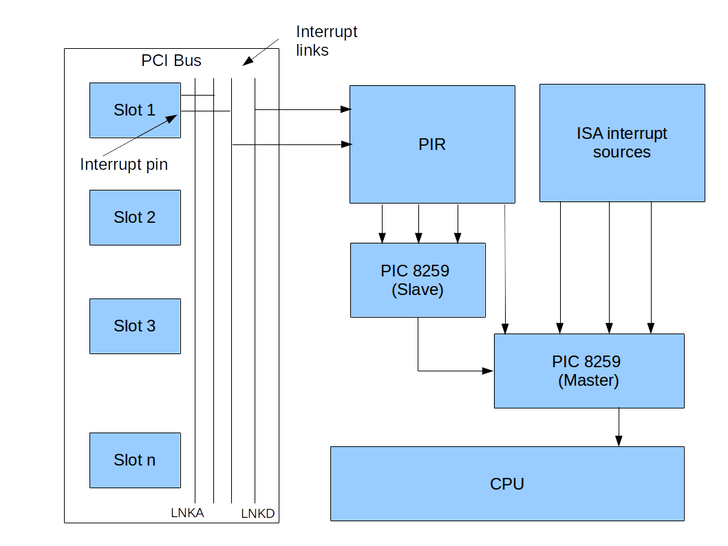
The exact mechanism how a hardware interrupt travels from a peripheral device to the CPU is one of the most complicated and bloated areas of the PC architecture. In most cases, there is an additional piece of hardware sitting between a device and the CPU that is responsible for handling this communication and is called the interrupt controller. The first IBM compatible PCs had an interrupt controller called the PIC that was able to handle eight different hardware interrupts. However, with an increasing number of devices, this soon turned out to be not sufficient, so a second interrupt controller was cascaded with the first one to be able to manage sixteen interrupts. This itself was made a bit more complicated than it sounds by the fact that at this time, two bus systems were around – the new PCI bus and the old ISA bus – and that the interrupt routing could be programmed by the BIOS using the so-called programmable interrupt router (PIR). So we already had a bit of a complex setup, as indicated in the diagram below.


Then the first PCs started to have more than one CPU, and a more flexible mechanism was invented – the APIC. Unfortunately, the old interrupt controller was still around and could be used, making for a very complex configuration mechanism. And finally, newer devices use a mechanism called MSI that avoids an interrupt controller almost completely. If you want to read up the full story, again the ctOS documentation has all the nitty-gritty details.

Where are interrupts used?

I started this post with the bold claim that interrupts are the heartbeat of a modern operating system kernel – so let me try to justify this statement.

First, let us think about how a CPU would typically communicate with the hardware. Take a very simple example – user input. Of course, in a dialogue driven programming style, things are simple. You would print something to the screen and then wait for user input. More specifically, you would periodically, maybe within every few microseconds, ask the keyboard controller for any new data that has arrived.

Such a design is simple, but has a major disadvantage: while you are actively waiting (polling in the language of computer scientists) for input, you consume CPU time and the CPU cannot do anything else. This is not a major problem for a home computer operating system of the early eighties, but turns into a problem when you want to support multi-tasking or even multi-user capabilities.

Interrupts offer a way out. Instead of sitting in a loop and polling for new data every few thousand iterations, the CPU can hand over control to another task which is currently not expecting user input and can let the keyboard controller fire an interrupt if the user presses (or releases) a key. The interrupt service handler can then inspect the input and either put it into a buffer for later processing or initiate a task switch back to the program waiting for the input (we will look in more detail into the exact mechanics of a task switch in a later post).

A similar mechanism can be used for other input/output related processing. If, for instance, we want to read data from the hard disk, we can apply a procedure called direct memory access (DMA). With DMA, the CPU would ask the hard disk controller to load one or more sectors from the disk and then continue to work on other tasks. The controller would – in the background – read the data from the disk and transfer it into a designated area of the systems main memory. Once the transfer is complete, it would inform the CPU by raising an interrupt. The CPU could then, again in an interrupt service handler, get the data and process it further. Similar mechanism apply for networking – incoming packets can trigger interrupts, or an interrupt could signal to the CPU that the network controller is ready to send out data.

But interrupts are not only useful for I/O related tasks – they are also a major ingredient for the implementation of multi-tasking. In fact, the very first multi-tasking systems used for home PCs where based on a design called cooperative multi-tasking. With that design, a task would actively return control to the operating system after executing some time to allow other processes to run. You might want to compare this to a group of people on a hot summer day sharing a bottle of water. When everybody cooperates and passes on the bottle after a few sips, this works fine. But things go wrong if someone – for whatever reasons – just keeps on drinking until the bottle is empty. Translated back to the world of operating systems, this design allows a single process to consume the entire CPU time, so that no other process can execute any more, for instance because it is stuck in an infinite loop due to a programming error – the machine will appear to hang. Those of you who have still seens Windows 3.11 that uses this design know what I am talking about.

A more advanced design can be realized using interrupts. A modern PC does for instance have a timer that creates interrupts at a defined frequency, say 1000 Hz, i.e. one interrupt every millisecond. If the interrupt service routine triggered by the timer is performing a task switch, it is made sure that even if a process hangs, control will be returned to the operating system and potentially to a different process after at most one millisecond. This design is called preemptive multitasking because the task switch is not actively initiated by the currently running process, but the process is interrupted (preeempted) by the ISR and the operating system.

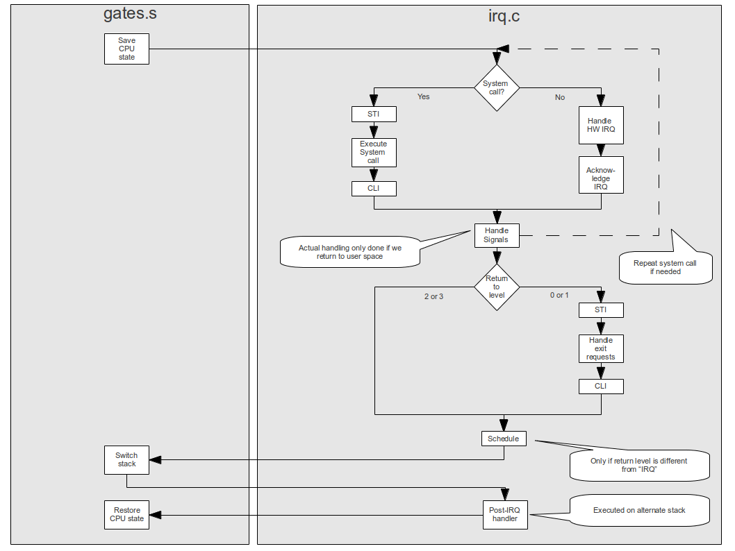
And there are even more applications that are worth being mentioned – you can use interrupts for debugging, several CPU cores can use special interrupts to communicate with each other and a thermal sensor can use an interrupt to let the CPU know that a certain temperature has been exceeded. In fact, in an operating system kernel, a lot of processing is done in an interrupt service handler, like dealing with hardware interrupts, scheduling a new task and handling signals – see the overview of the interrupt processing in ctOS below to get an idea.

There is one more point that we have ignored so far – interrupts can be used to switch back between kernel space and user space, or between ring 3 and ring 0 of a CPU. However, explaining this requires a basic understanding of the protected mode, so we will leave this for a later post.

Get your kernel going – the boot process

Most careers in operating system development probably start with a seemingly simple task – produce a program that, at start time, takes full control of a computer and prepares for the execution of the actual operating system, i.e. boot the computer. It turns out, however, that – thanks to the complexity of modern x86 based hardware – this is easier said than done. In this post, we will look at the boot process in a bit more detail.

History of the boot process

To understand the boot process in a modern PC, it is actually useful to go back into the past a bit. The first home computer that I owned was an Amstrad CPC 464 with a Zilog Z80 CPU. Like any other CPU I am aware of, this CPU stores the memory location of the next instruction to be executed in a register, called – in this case – the program counter (PC). When you turn on that machine, the CPU is in its initial state, with the value of the PC being equal to its initial value 0x0000. Now, at this point in memory space, there was actually no RAM, but a ROM that contained the CPC firmware. Starting at address 0x0000, the so-called restart block was located which then took over and initialized the system. And let the fun begin …(picture taken on the fabulous CPCBox, a browser-based CPC emulator).

cpc4641.png

This mechanism is straightforward and fast – when you turn on the machine, the operating system is available immediately and you can start to work with it. However, there are obvious disadvantages, the most important one being that updates are difficult once a machine is shipped, and even late in the manufacturing process.

The developers of the famous IBM PC XT decided to use a different approach. Instead of loading the full operating system from ROM, the ROM did only contain a firmware called the BIOS, a small set of routines needed for some basic operations, like reading from the hard drive or a disk, and a short startup routine. When the system comes up, the CPU again starts execution at some predefined point in memory, where the BIOS startup routine is located. This routine would then typically execute some self-tests and then load the actual operating system from the hard drive or a floppy disk.

Loading the operating system does actually happen in two phases. In the first phase, the BIOS loads the so-called boot loader. The boot loader is located at a fixed location of the hard drive, specifically in the first sector (called the master boot record (MBR)), and occupies a bit less than 512 bytes. This boot loader is brought into memory and then executed. It is then responsible for locating the actual operating system and loading it.

So far, this is comparatively simple. Unfortunately, PC hardware then started to evolve, and with every step in the evolution, the boot process had to be adapted so that it could make use of new features, but still be backwards compatible. For instance, when the x86 CPU was enhanced by adding the so-called protected mode in 1985, the BIOS would still operate in the older real mode to stay compatible with legacy operating systems. When an operating system wanted to make use of the new features of the protected mode, either the boot loader or the early stages of the operating system kernel had to switch the CPU into protected mode. However, as the BIOS is still 16 bit code, its routines can no longer be accessed once that switch has been completed, in particular reading from a hard drive is no longer easily possible until the initialization of the operating system has reached a certain point. This makes for interesting chicken-and-egg problems: if the operating system that needs to be loaded exceeds a certain size, you will have to switch to protected mode to be able to utilize the full memory, but once this is done it becomes much more complicated to access the hard drive to load the operating system files.

To solve this, several sophisticated boot mechanisms were implemented by various boot loaders. One approach was to actually compress the operating system image so that it could be loaded into memory once the BIOS was still accessible, then perform the switch to protected mode and then decompress the image. Another approach is to boot the system in several stages. The boot code for stage 0 would, for instance, be stored in the MBR, which would then load a stage 1. This stage 1 would contain sufficient functionality to read data from a standard file system, including a hard disk driver. It would then switch to protected mode and use this functionality to load the stage 2, which would then start the actual operating system. The GRUB bootloader, for instance, uses a similar (but slightly different) mechanism.

Booting a modern PC

Roughly around 2005, the industry started to introduce the UEFI as the next generation standardized PC firmware, aiming to become the successor of the outdated BIOS. The UEFI is much more powerful than the BIOS. Instead of loading one sector from a specified location on the hard drive, the UEFI is able to read from a file system. Thus the initial operating system image can be an ordinary executable file, stored on a file system. The UEFI will search certain standard directories for files with predefined names (like BOOTX64.EFI) and execute such a file if it is found. This file then executes in an UEFI environment in 32 bit protected mode or 64 bit long mode and has access to UEFI services to perform operations like input, output or hard drive access. These services can then be used to load the operating system, before eventually control of the system is handed over to the operating system and the UEFI services must no longer be used.

However, the BIOS used to be more than just a set of routines – it also contained several configuration tables that provide basic information on the hardware relevant for the operating system, like the available graphics modes, the number and type of available CPUs, the available memory and reserved memory areas and information on the configuration of the system interrupts. This information is now presented to an operating system as part of the ACPI (Advanced configuration and power interface). The ACPI is a complex collection of tables, some of which are static, some of which are actually dynamic, i.e. contain byte code that needs to be run by a bytecode interpreter.

So far, the description has focused on the standard case for a home PC – booting from a local storage like hard drive, an USB stick or a CD-ROM. However, several methods exist to boot over a network as well. The PXE boot protocol, for example, is a mechanism to boot an operating system over a network. When PXE boot is used, either a boot loader or a sufficiently modern BIOS initializes the clients network card and establishes a connection to server. The server runs a TFTP server (TFTP is a simplified version of the FTP protocol) and the client uses the TFTP protocol to transfer an operating system image over the network. This is the technology behind thin clients, i.e. clients that only contain a ROM based firmware capable of executing a PXE based boot process, but no local storage and no local copy of the operating system.

To get an idea how the full boot process looks like on a modern PC, let us take a look at the sequence of steps that are executed when my homebrew operating system ctOS starts up. Here is a screenshot of the system once the startup sequence is completed (taken using the QEMU emulator).

ctOS_Startup

The most important steps that actually execute in the background and produce this output are as follows.

  1. The hardware (or the emulator) loads the BIOS (SeaBIOS in this case)
  2. The BIOS locates the boot loader (GRUB2 in my case) on the hard drive and loads it in several stages
  3. GRUB2 starts to execute on the first CPU in the system, called the bootstrap CPU
  4. When GRUB2 hands over control to the operating system, the system is already in protected mode, however certain system tables are in a preliminary or incomplete state. Thus these tables are initialized first
  5. Then all components of the kernel are initialized. This includes device drivers, interrupts, the memory manager, the process manager and the TCP/IP stack.
  6. During this stage, the system will also read the BIOS or ACPI configuration tables and detect and initialize other hardware components like the interrupt controller, the system clock, the keyboard, or attached PCI devices like hard drives and network cards

  7. Next, all the other CPUs in the system are initialized and put into protected mode
  8. Finally, the root process is started and the command line interface is located on the disk and started – at this point the boot process is complete and the user takes over control of the system

Of course for a more advanced operating system, the actual boot process would do much more – loading a graphical user interface, for instance, or starting system daemons. However, technically, once we get to the point that a user space program can execute, most of the low level subtleties are mastered and we can work in a stable environment.

This concludes our discussion of the boot process. With the next post in this series, I will start our trip through the various components of an operating system. Happy booting!

Why building an operating system from scratch?

What happens if you turn on a PC? How is an operating system able to run multiple tasks in parallel? What happens if you hit a key on your keyboard? And what actually is a process? If you have ever thought for more than a second about one of these things, then read on…

A few years back, actually in late 2010 or early 2011, I was at a point where my growing interest in computer science naturally lead me to those questions. So I did what most of us would probably do – I started to search for information on this and tried to understand what I got.

One day, I hit upon a tutorial that explained the boot process of a PC, and actually contained a short instruction on how to write a very simple program that would act as a boot loader – you would copy this program to a floppy disk (yes, that still existed in some machines at this time) or a CD-ROM and boot from there, and – voila – instead of a Windows or Linux coming up, the system would run your program and print some deep wisdom like “Hello World!” onto the screen.

Now printing something is easy, but what if I wanted the user to be able to enter something and print a response? Obviously, this requires some sort of communication with the keyboard and there is no operating system around that can help you with that, so I needed to learn about a thing called keyboard controller. But wait, why could I only use a few kB of memory? I found that I needed to switch from real mode to protected mode, install interrupt handlers … and slowly, the attempt to just build something that would boot turned into more.

Over the next roughly 18 months, I continued to walk down this path, and eventually had build a small Unix operating system kernel. I then added a simple command line interface, graphics mode and a C library and eventually got to a point where I was able to take simple programs originally written for Linux or other Unix-like operating systems, and compile and run them on my new operating system, which I did call ctOS. Here is a screenshot – my OS is running in a virtual machine on the left, and on the right you see a few measurements of the physical CPU load while running some multi-threading tests within ctOS.

ctOS_SMP_Test

As you might imagine, this required quite some work, and I eventually got to a point where I spend more time working on other things and further development came to an end.

Earlier this year, I was cleaning up a few things on my hard drive and – more or less by accident – hit upon my old code archive again. Being a curious person, I was wondering whether I would still be able to compile and run the system – and of course it badly failed when I tried it. This was not really surprising – my development environment had changed from a 32 bit system to a 64 bit system, and the emulators that I used to run and test the OS had changed quite a bit as well, fixing defects that did actually hide away some bugs in my OS. And of course the “average PC” had changed quite a lot since 2011. The BIOS is now a thing of the past, PCs use UEFI to boot and ACPI tables to store their configuration instead of BIOS tables, and you will hardly ever find a system with a floppy disk drive and only one CPU any more.

So I decided to invest some time to make my OS work again and to adapt it to the current generation of hardware. This included building a new development environment, fixing some defects that become suddenly apparent as the emulator had changed, making the system ACPI aware, removing all dependencies on the BIOS etc. I did also clean up the source code and migrated everything to a Github repository and added a few additional ports.

I have a realistic view on how much time I will probably have in the future to further develop and improve my OS. However, it can still serve a purpose – education. After all, this is what it was created for: helping me to understand some of the inner workings of an operating system.

In fact, my plan is to publish a series of blog posts on the principles and structures behind a Unix operating system, using ctOS to illustrate these concepts and linking to the documentation I have created over the years for the details. This will cover topics like the overall structure of an operating system, processes and the scheduler, interrupts, memory management, device driver and the networking stack. So if you ever wanted to understand how an operating system really works this is the time for you to learn it – stay tuned and join me again for the first part of the series. Until then, you might want to check out the ctOS source code on Github and the documentation that comes with it – if you want, you can even download some of the binary packages on the release page and play with it.

Networking basics – the layered networking model

Recently, I picked up an old project of mine – implementing a Unix like operating kernel from scratch. I will post more on this later, but one of the first things I stumbled across when browsing my old code and my old documentation was the networking stack. I used this as an opportunity to refresh my own understanding of networking basics, and reckoned it might help others to post my findings here. So I decided to write a short series of posts on the basics of networking – ethernet, ARP, IP, TCP/UDP and all that stuff.

Before we start to get into details on the different networking technologies, let me first explain the idea of a layered networking architecture.

Ultimately, networking is about physical media (copper cables, for instance) connecting physical machines. Each of these machines will be connected to the network using a network adapter. These adapters will write messages into the network, i.e. create a certain sequence of electrical signals on the medium, and read other messages coming from the network.

However, the magic of a modern networking architecture is that the same physical network can be used to connect different machines with different operating systems using different networking protocols. When you use your web browser to connect to some page on the web – this one for instance – your web browser will use a protocol called HTTP(S) for that purpose. From the web browsers point of view, this appears to be a direct connection to the web server. The underlying physical network can be quite different – it can be a combination of Ethernet or WLAN to connect your PC to a router, some technology specific to your ISP or even a mobile network. The beauty of that is that the browser does not have to care. As often in computer science, this becomes possible by an abstract model organizing networking capabilities into layers.

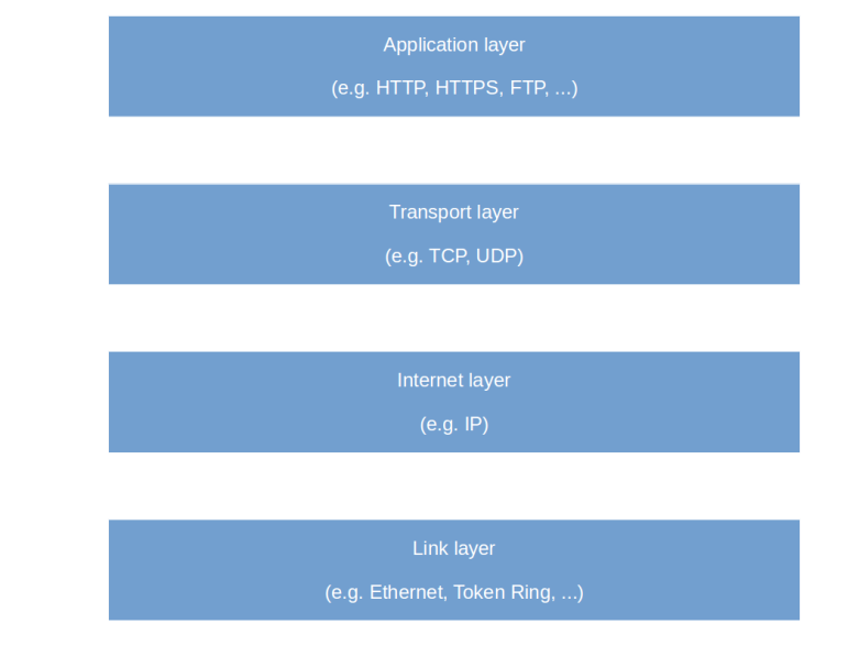
Several models for this layering exist, like the OSI model and the TCP/IP layered model defined in RFC1122. For the sake of simplicity, let us use the four-layer TCP/IP model as an example.


TCPIPLayers


The lowest layer in this model is called the link layer. Roughly speaking, this layer is the layer which is responsible for the actual physical connection between hosts. This covers things like the physical media connecting the machines and the mechanisms used to avoid collisions on the media, but also the addressing of network interfaces on this level.

One of the most commonly used link layer protocols is the Ethernet protocol. When the Ethernet protocol is used, hosts in the network are addressed using the so-called MAC address which uniquely identifies a network card within the network. In the Ethernet protocol (and probably in most other protocols), the data is transmitted in small units called packets or frames. Each packet contains a header with some control data like source and destination, the actual data and maybe a checksum and some end-of-data marker.

Now Ethernet is the most common, but by far not the only available link layer protocol. Another protocol which was quite popular at some point at the end of the last century is the Token Ring protocol, and in modern networks, a part of the path between two stations could be bridged by a provider specific technology or a mobile network. So we need a way to make hosts talk to each other which are not necessarily connected via a direct Ethernet link.

The approach taken by the layered TCP/IP model to this is as follows. Suppose you have – as in the diagram below – two sets of machines that are organized in networks. On the left hand side, we see an Ethernet network with three hosts that can talk to each other using Ethernet. On the right hand side, there is a smaller network that consists of two hosts, also connected with each other via Ethernet (this picture is a bit misleading, as in a real modern network, the topology would be different, but let us ignore this for a moment).

NetworksAndGatewaysBoth networks are connected by a third network, indicated by the dashed line. This network can use any other link layer technology. Each network contains a dedicated host called the gateway that connects the network to this third network.

Now suppose host A wants to send a network message to host B. Then, instead of directly using the link layer protocol in its network, i.e. Ethernet, it composes a network message according to a protocol that is in the second layer of the TCP/IP networking model, called the Internet layer which uses the IP protocol. Similar to an Ethernet packet, this IP packet contains again a header with target and source address, the actual data and a checksum.

Then host A takes this message, puts that into an Ethernet packet and sends it to the gateway. The gateway will now extract the IP message from the Ethernet packet, put it into a message specific to the networking connecting the two gateways and transmit this message.

When the message arrives at the gateway on the right hand side, this gateway will again extract the IP message, put it into an Ethernet message and send this via Ethernet to host B. So eventually, the unchanged IP message will reach host B, after traveling through several networks, piggybacked on messages specific to the used network protocols. However, for applications running on host A and B, all this is irrelevant – they will only get to see IP messages and do not have to care about the details and layer below.

In this way, the internet connects many different networks using various different technologies – you can access hosts on the internet from your mobile device using mobile link layer protocols, and still communicate with a host in a traditional data center using Ethernet or something else. In this sense, the internet is a network of networks, powered by the layer model.

But we are not yet done. The IP layer is nice – it allows us to send messages across the internet to other hosts, using the addresses specific to the IP layer (yes, this is the IP address). But it does, for instance, not yet guarantee that the message ever arrives, nor does it provide a way to distinguish between different communication end points (aka ports) on one host.

These items are the concern of the next layer, the transport layer. The best known example of a transport layer protocol is TCP. On top of IP, TCP offers features like stream oriented processing, re-transmission of lost messages and ports as additional address components. For an application using TCP, a TCP connection appears a bit like a file into which bytes can be written and out of which bytes can be read, in a well defined order and with guaranteed delivery.

Finally, the last layer is the application layer. Common application layer protocols are HTTP (the basis of the world wide web), FTP (the file transfer protocol), or SMTP (the mail transport protocol).

The transitions between the different layers work very much like the transition between the internet layer and the link layer. For instance, if an application uses TCP to send a message, the operating system will take the message (not exactly true, as TCP is byte oriented and not message oriented, but let us gracefully ignore this), add a TCP header, an IP header and finally an Ethernet header, and ask the network card to transmit the message on the Ethernet network. When the message is received by the target host, the operating system of that host strips off the various headers one by one and finally obtains the original data sent by the first host.

The part of the operating system responsible for this mechanism is naturally itself organized in layers  – there could for instance be an IP layer that receives data from higher layers without having to care whether the data represents a TCP message or a UDP message. This layer then adds an IP header and forwards the resulting message to another layer responsible for operating the Ethernet network device and so forth. Due to this layered architecture stacking different components on top of each other, the part of the operating system handling networking is often called the networking stack. The Linux kernel, for instance, is loosely organized in this way (see for instance this article).

This completes our short overview of the networking stack. In the next few posts, we will look at each layer one by one, getting our hands dirty again, i.e. we will create and inspect actual network messages and see the entire stack in action.