
So far, our OpenStack control plane setup was rather simple – we had a couple of compute nodes, and all other services were running on the same controller node. In practice, this does not only create a single point of failure, but also a fairly high traffic on the network interfaces. In this post, we will move towards a more distributed setup with a dedicated network node.
OpenStack nodes and their roles
Before we plan our new topology, let us quickly try to understand what nodes we have used so far. Recall that each node has an Ansible hostname which is the name returned by the Ansible variable inventory_hostname and defined in the inventory file. In addition, each node has a DNS name, and during our installation procedure, we adapt the /etc/hosts file on each node so that DNS names and Ansible hostnames are identical. A host called, for instance, controller in the Ansible inventory will therefore be reachable under this name across the cluster.
The following table lists the types of nodes (defined by the services running on them) and the Ansible hostnames used so far.
| Node type | Description | Hostname |
|---|---|---|
| api_node | Node on which all APIs are exposed. This will typically be the controller node, but could also be a load balancer in a HA setup | controller |
| db_node | Node on which the database is running | controller |
| mq_node | Node on which the Rabbit MQ service is running | controller |
| memcached_node | Node on which the memcached service is running | controller |
| ntp_node | Node on which the NTP service is running | controller |
| network_node | Node on which DHCP agent and the L3 agent (and thus routers) are running | controller |
| horizon_node | Node on which Horizon is running | controller |
| compute_node | Compute nodes | compute* |
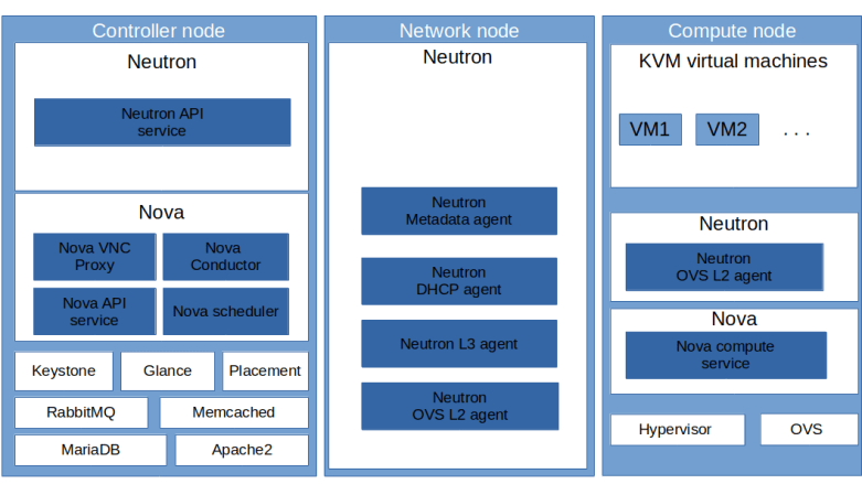
Now we can start to split out some of the nodes and distribute the functionality across several machines. It is rather obvious how to do this for e.g. the database node or the RabbitMQ node – simply start MariaDB or the RabbitMQ service on a different node and update all URLs in the configuration accordingly. In this post, we will instead introduce a dedicated network node that will hold all our Neutron agents. Thus the new distribution of functionality to hosts will be as follows.
| Node type | Description | Hostname |
|---|---|---|
| api_node | Node on which all APIs are exposed. This will typically be the controller node, but could also be a load balancer in a HA setup | controller |
| db_node | Node on which the database is running | controller |
| mq_node | Node on which the Rabbit MQ service is running | controller |
| memcached_node | Node on which the memcached service is running | controller |
| ntp_node | Node on which the NTP service is running | controller |
| network_node | Node on which DHCP agent and the L3 agent (and thus routers) are running | network |
| horizon_node | Node on which Horizon is running | controller |
| compute_node | Compute nodes | compute* |
Here is a diagram that summarizes our new distribution of components to the various VirtualBox instances.
In addition, we will make a second change to our network topology. So far, we have used a setup where all machines are directly connected on layer 2, i.e. are part of a common Ethernet network. This did allow us to use flat networks and VLAN networks to connect our different nodes. In reality, however, an OpenStack cluster will might sometimes be operated on top of an IP fabric so that layer 3 connectivity between all nodes is guaranteed, but we cannot assume layer 2 connectivity. Also, broadcast and multicast traffic might be restricted – an example could be an existing bare-metal cloud environment on top of which we want to install OpenStack. To be prepared for this situation, we will change our setup to avoid direct layer 2 connectivity. Here is our new network topology implementing these changes.
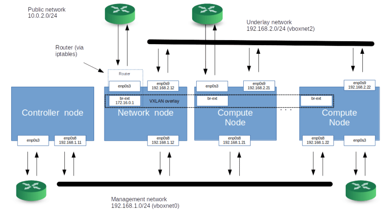
This is a bit more complicated than what we used in the past, so let us stop for a moment and discuss the setup. First, each node (i.e. each VirtualBox instance) will still be directly connected to the network on our lab host by a VirtualBox NAT interface with IP 10.0.2.15, and – for the time being – we continue to use this interface to access our machines via SSH and to download packages and images (this is something which we will change in an upcoming post as well). Then, there is still a management network with IP range 192.168.1.0/24.
The network that we did call the provider network in our previous posts is now called the underlay network. This network is reserved for traffic between virtual machines (and OpenStack routers) realized as a VXLAN virtual OpenStack network. As we use this network for VXLAN traffic, the network interfaces connected to it are now numbered.
All compute nodes are connected to the underlay network and to the management network. The same is true for the network node, on which all Neutron agents (the DHCP agent, the L3 agent and the metadata agent) will be running. The controller node, however, is not connected to the underlay network any more.
But we need a bit more than this to allow our instances to connect to the outside world. In our previous posts, we did build a flat network that was directly connected to the physical infrastructure to provide access to the public network. In our setup, where direct layer 2 connectivity between the machines can no longer be assumed, we realize this differently. On the network node and on each compute node, we bring up an additional OVS bridge called the external bridge br-ext. This bridge will essentially act as an additional virtual Ethernet device that is used to realize a flat network. All external bridges will be connected with each other by a VXLAN that is not managed by OpenStack, but by our Ansible scripts. For this VXLAN, we use a segmentation ID which is different from the segmentation IDs of the tenant networks (as all VXLAN connections will use the underlay network IP addresses and the standard port 4789, this isolation is required).
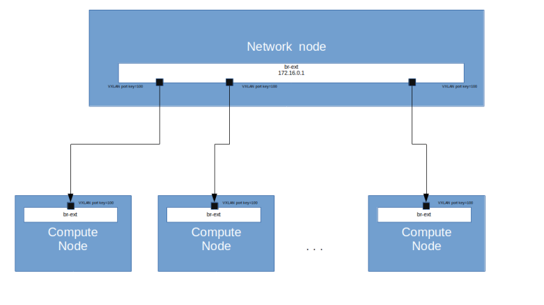
Essentially, we use the network node as a virtual bridge connecting all compute nodes with the network node and with each other. For Neutron, the external bridges will look like a physical interface building a physical network, and we can use this network as supporting provider network for a Neutron flat network to which we can attach routers and virtual machines.
This setup also avoids the use of multicast traffic, as we connect every bridge to the bridge running on the network node directly. Note that we also need to adjust the MTU of the bridge on the network node to account for the overhead of the VXLAN header.
On the network node, the external bridge will be numbered with IP address 172.16.0.1. It can therefore, as in the previously created flat networks, be used as a gateway. To establish connectivity from our instances and routers to the outside world, the network node will be configured as a router connecting the external bridge to the device enp0s3 so that traffic can leave the flat network and reach the lab host (and from there, the public internet).
MTU settings in Neutron
This is a good point in time to briefly discuss how Neutron handles MTUs. In Neutron, the MTU is an attribute of each virtual network. When a network is created, the ML2 plugin determines the MTU of the network and stores it in the Neutron database (in the networks table).
When a network is created, the ML2 plugin asks the type driver to calculate the MTU by calling its method get_mtu. For a VXLAN network, the VXLAN type driver first determines the MTU of the underlay network as the minimum of two values:
- the globally defined MTU set by the administrator using the parameter global_physnet_mtu in the neutron.conf configuration file (which defaults to 1500)
- the path MTU, defined by the parameter path_mtu in the ML2 configuration
Then, 50 bytes are subtracted from this value to account for the VXLAN overhead. Here 20 bytes are for the IPv4 header (so Neutron assumes that no options are used) and 30 bytes are for the remaining VXLAN overhead, assuming no inner VLAN tagging (you might want to consult this post to understand the math behind this). Therefore, with the default value of 1500 for the global MTU and no path MTU set, this results in 1450 bytes.
For flat networks, the logic is a bit different. Here, the type driver uses the minimum of the globally defined global_physnet_mtu and a network specific MTU which can be defined for each physical network by setting the parameter physical_network_mtus in the ML2 configuration. Thus, there are in total three parameters that determine the MTU of a VXLAN or flat network.
- The globally defined global_physnet_mtu in the Neutron configuration
- The per-network MTU defined in physical_network_mtus in the ML2 configuration which can be used to overwrite the global MTU for a specific flat network
- The path MTU in the ML2 configuration which can be used to overwrite the global MTU of the underlay network for VXLAN networks
What does this imply in our case? In the standard configuration, the VirtualBox network interfaces have an MTU of 1500, which is the standard Ethernet MTU. Thus we set the global MTU to 1500 and leave the path MTU undefined. With these settings, Neutron will correctly derive the MTU 1450 for interfaces attached to a Neutron managed VXLAN network.
Our own VXLAN network joining the external bridges is used as supporting network for a Neutron flat network. To tell Neutron that the MTU of this network is only 1450 (the 1500 of the underlying VirtualBox network minus 50 bytes for the encapsulation overhead), we can set the MTU for this network explicitly in the physical_network_mtus configuration item.
Implementation and tests
Let us now take a closer look at how our setup needs to change to make this work. First, obviously, we need to adapt our Vagrantfile to bring up an additional node and to reflect the changed network configuration.
Next, we need to bring up the external bridge br-ext on the network node and on the compute nodes. On each compute node, we create a VXLAN port pointing to the network node, and on the network node, we create a corresponding VXLAN port for each compute node. All VXLAN ports will be assigned to the VXLAN ID 100 (using the option:key= option of OVS). We then add a flow table entry to the bridge which defines NORMAL processing for all packets, i.e. forwarding like an ordinary switch.
We also need to make sure that the external bridge interface on the network node is up and that it has an IP address assigned, which will automatically create a route on the network node as well.
The next step is to configure the network node as a router. After having set the famous flag in /proc/sys/net/ipv4/ip_forward to 1 to enable forwarding, we need to set up the necessary rules in iptables. Here is a sample iptables-save file that demonstrates this setup.
# Set policies for raw table to accept
*raw
:PREROUTING ACCEPT [0:0]
:OUTPUT ACCEPT [0:0]
COMMIT
# Set policies for NAT table to ACCEPT and
# add SNAT rule for traffic going out via the public interface
# Generated by iptables-save v1.6.1 on Mon Dec 16 08:50:33 2019
*nat
:PREROUTING ACCEPT [0:0]
:INPUT ACCEPT [0:0]
:OUTPUT ACCEPT [0:0]
:POSTROUTING ACCEPT [0:0]
-A POSTROUTING -o enp0s3 -j MASQUERADE
COMMIT
# Set policies in mangle table to ACCEPT
*mangle
:PREROUTING ACCEPT [0:0]
:INPUT ACCEPT [0:0]
:FORWARD ACCEPT [0:0]
:OUTPUT ACCEPT [0:0]
:POSTROUTING ACCEPT [0:0]
COMMIT
# Set policy for forwarded traffic in filter table to DROP, but allow
# forwarding for traffic coming from br-ext and established connections
# Also block incoming traffic on the public interface except SSH traffic
# and reply to connected traffic
# Do not set the INPUT policy to DROP, as this would also drop all traffic
# on the management and underlay networks
*filter
:INPUT ACCEPT [0:0]
:FORWARD DROP [0:0]
:OUTPUT ACCEPT [0:0]
-A FORWARD -i br-ext -j ACCEPT
-A FORWARD -i enp0s3 -m conntrack --ctstate RELATED,ESTABLISHED -j ACCEPT
-A INPUT -i enp0s3 -p tcp --destination-port 22 -j ACCEPT
-A INPUT -i enp0s3 -m conntrack --ctstate RELATED,ESTABLISHED -j ACCEPT
-A INPUT -i enp0s3 -j DROP
-A INPUT -i br-ext -m conntrack --ctstate RELATED,ESTABLISHED -j ACCEPT
-A INPUT -i br-ext -p icmp -j ACCEPT
-A INPUT -i br-ext -j DROP
COMMIT
Let us quickly discuss these rules. In the NAT table, we set up a rule to apply IP masquerading to all traffic that goes out on the public interface. Thus, the source IP address will be replaced by the IP address of enp0s3 so that the reply traffic is correctly routed. In the filter table, we set the default policy in the FORWARD chain to DROP. We then explicitly allow forwarding for all traffic coming from br-ext and for all traffic coming from enp0s3 which belongs to an already established connection. This is the firewall part of the rules – all traffic not matching one of these rules cannot reach the OpenStack networks. Finally, we need some rules in the INPUT table to protect the network node itself from unwanted traffic from the external bridge (to avoid attacks from an instance) and from the public interface and only allow reply traffic and SSH connections. Note that we make an exception for ICMP traffic so that we can ping 172.16.0.1 from the flat network – this is helpful to avoid confusion during debugging.
In addition, we use an OVS patch-port to connect our external bridge to the bridge br-phys, as we would do it for a physical device. We can then proceed to set up OpenStack as before, with the only difference that we install the Neutron agents on our network node, not on the controller node. If you want to try this out, run
git clone https://github.com/christianb93/openstack-labs
cd openstack-labs/Lab10
vagrant up
ansible-playbook -i hosts.ini site.yaml
ansible-playbook -i hosts.ini demo.yaml
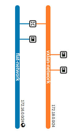
The playbook demo.yaml will again create two networks, one VXLAN network and one flat network, and will start one instance (demo-instance-3) on the flat network and two instances on the VXLAN network. It will also install a router connecting these two networks, and assign a floating IP address to the first instance on the VXLAN network.
As before, we can still reach Horizon from the lab host via the management network on 192.168.1.11. If we navigate to the network topology page, we see the same pattern that we have already seen in the previous post.
Let us now try out a few things. First, let us try to reach the instance demo-instance-3 from the network node. To do this, log into the network node and ssh into the machine from there (replacing 172.16.0.9 with the IP address of demo-instance-3 on the flat network, which might be different in your case).
vagrant ssh network
ssh -i demo-key cirros@172.16.0.9
Note that we can no longer reach the machine from the lab host, as we are not using the VirtualBox network vboxnet1 any more. We can, however, SSH directly from the lab host (!) into this machine using the network node as a jump host.
ssh -i ~/.os_credentials/demo-key \
    -o StrictHostKeyChecking=no \
    -o "ProxyCommand ssh -i .vagrant/machines/network/virtualbox/private_key \
      -o StrictHostKeyChecking=no \
      -o UserKnownHostsFile=/dev/null \
      -p 2200 -q \
      -W 172.16.0.9:22 \
      vagrant@127.0.0.1" \
    cirros@172.16.0.9
What about the instances on the VXLAN network? Our demo playbook has created a floating IP for one of the instances which you can either take from the output of the playbook or from the Horizon GUI. In my case, this is 172.16.0.4, and we can therefore reach this machine similarly.
ssh -i ~/.os_credentials/demo-key \
    -o StrictHostKeyChecking=no \
    -o "ProxyCommand ssh -i .vagrant/machines/network/virtualbox/private_key \
      -o StrictHostKeyChecking=no \
      -o UserKnownHostsFile=/dev/null \
      -p 2200 -q \
      -W 172.16.0.4:22 \
      vagrant@127.0.0.1" \
    cirros@172.16.0.4
Now let us try to reach a few target IP addresses from this instance. First, you should be able to ping the machine on the flat network, i.e. 172.16.0.9 in this case. This is not surprising, as we have created a virtual router connecting the VXLAN network to the flat network. However, thanks to the routing functionality on the network node, we should now also be able to reach our lab host and other machines in the network of the lab host. In my case, for instance, the lab host is connected to a cable modem router with IP address 192.168.178.1, and in fact pinging this IP address from demo-instance-1 work just fine. You should even be able to SSH into the lab host from this instance!
It is interesting to reflect on the path that this ping request takes through the network.
- First, the request is routed to the default gateway 172.18.0.1 network interface eth0 on the instance
- From there, the packet travels all the way down via the integration bridge to the tunnel bridge on the compute node, via VXLAN to the tunnel bridge on the network node, to the integration bridge on the network node and to the internal port of the router
- In the virtual OpenStack router, the packet is forwarded to the gateway interface and reaches the integration bridge again
- As we are now on the flat network, the packet travels from the integration bridge to the physical bridge br-phys and from there to our external bridge br-ext. In the OpenStack router, a first NAT’ing takes place which replaces the source IP address of the packet by 172.18.0.1
- The packet is received by the network node, and our iptables rules become effective. Thus, a second NAT’ing happens, the IP source address is set to that of enp0s3 and the packet is forwarded to enp0s3
- This device is a VirtualBox NAT device. Therefore VirtualBox now opens a connection to the target, replaces the source IP address with that of the outgoing lab host interface via which this target can be reached and sends the packet to target host
If we log into the instance demo-instance-3 which is directly attached to the flat network, we are of course also able to reach our lab host and other machines to which it is directly connected, essentially via the same mechanism with the only difference that the first three steps are not necessary.
There is, however, still one issue: DNS resolution inside the instances does not work. To fix this, we will have to set up our DHCP agent, and this agent and how it works will be the topic of our next post.

3 Comments