Setting up our OpenStack playground

In this post, we will describe the setup of our Lab environment and install the basic infrastructure services that OpenStack uses.

Environment setup

In a real world setup, OpenStack runs on a collection of physical servers on which the virtual machines provided by the cloud run. Now most of us will probably not have a rack in their basement, so that using four or five physical servers for our labs is not a realistic option. Instead, we will use virtual machines for that purpose.

To avoid confusion, let us first fix some terms. First, there is the actual physical machine on which the labs will run, most likely a desktop PC or a laptop, and most likely the PC you are using to read this post. Let us call this machine the lab host.

On this host, we will run Virtualbox to create virtual machines. These virtual machines will be called the nodes, and they will play the role that in a real world setup, the physical servers would play. We will be using one controller node on which most of the OpenStack components will run, and two compute nodes.

Inside the compute nodes, the Nova compute service will then provision virtual machines which we call VMs. So effectively, we use nested virtualization – the VM is itself running inside a virtual machine (the node).

To run the labs, your host will need to have a certain minimum amount of RAM. When I tested the setup, I found that the controller node and the compute nodes in total consume at least 7-8 GB of RAM, which will increase depending on the number of VMs you run. To still be able to work on the machine, you will therefore need at least 16 GB of RAM. If you have more – even better. If you have less, you might also want to use a cloud based setup. In this case, the host could itself be a virtual machine in the cloud, or you could use a bare-metal provider like Packet to get access to a physical host with the necessary memory.

Not every cloud will work, though, as it needs to support nested virtualization. I have tested the setup on DigitalOcean and found that it works, but other cloud providers might yield different results.

Networking

Let us now take a look at the network configuration that we will use for our hosts. If you run OpenStack, there will be different categories of traffic between the nodes. First, there is management traffic, i.e. communication between the different components of the platform, like messages exchanged via RabbitMQ or API calls. For security and availability reasons, this traffic is typically handled via a dedicated management network. The management network is configured by the administrator and used by the OpenStack components.

Then, there is traffic between the VMs, or, more precisely, between the guests running inside the VMs. The network which is supporting this traffic is called the guest network. Note that we are not yet talking about a virtual network here, but about the network connecting the various nodes which eventually will be used for this traffic.

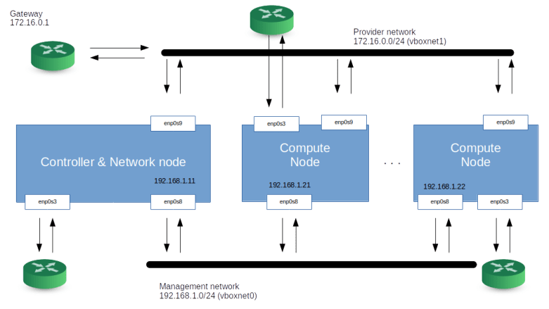
Sometimes, additional network types need to be considered, there could for instance be a dedicated API network to allow end users and administrators access to the API without depending on any of the other networks, or a dedicated external network that connects the network node to a physical route to provide internet access for guests, but for this setup, we will only use a two networks – a management network and a guest network. Note that the guest network needs to be provided by an adminstrator, but is controlled by Openstack (which, for instance, will add the interfaces that make up the network to virtual bridges so that they can no longer be used for other traffic).

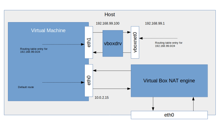
In our case, both networks, the management network and the guest network, will be set up as Virtualbox host-only networks, connecting our nodes. Here is a diagram that summarizes the network topology we will use.

OpenStackEnvironment

Setting up your host and first steps

Let us now roll up our sleeves and dive right into the first lab. Today, we will bring up our environment, and, on each node, install the required infrastructure like MySQL, RabbitMQ and so forth.

First, however, we need to prepare our host. Obviously, we need some tools installed – Vagrant, Virtualbox and Ansible. We will also use pwgen to create credentials. How exactly these tool need to be installed depends on your Linux distribution, on Ubuntu, you would run

sudo apt-get install python3-pip
pip3 install 'ansible==v2.8.6' 
sudo apt-get install pwgen
sudo apt-get install virtualbox
sudo apt-get install vagrant

The Ansible version is important. I found that there is at least oneissue which breaks network creation in OpenStack with Ansible with some 2.9.x versions of Ansible.

When we set up our labs, we will sometimes have to throw away our environment and rebuild it. This will be fully automated, but it implies that we need to download packages into the nodes over and over again. To speed up this process, we install a local APT cache. I use APT-Cacher-NG for that purpose. Installing it is very easy, simply run

sudo apt-get install apt-cacher-ng

This will install a proxy, listening on port 3142, which will create local copies of packages that you install. Later, we will instruct the apt processes running in our virtual machines to use this cache.

Now we are ready to start. First, you will have to clone my repository to get a copy of the scripts that we will use.

git clone https://github.com/christianb93/openstack-labs
cd openstack-labs/Lab1

Next, we will bring up our virtual machines. There is, however, a little twist when it comes to networking. As mentioned above, we will use Virtualbox host networking. As you might know when you have read my previous post on this topic, Virtualbox will create two virtual devices to support this, one for each network. These devices will be called vboxnet0 and vboxnet1. However, if these devices already exist, Virtualbox will use them and take over parts of the existing network configuration. This can lead to problems later, if, for instance, Virtualbox runs a DHCP server on this device, this will conflict with the OpenStack DHCP agent and your VMs will get incorrect IP addresses and will not be reachable. To avoid this, we will delete any existing interfaces (which of course requires that you stop all other virtual machines) and recreate them before we bring up our machines. The repository contains a shells script to do this. To run it and start the machines, enter

../scripts/createVBoxNetworks.sh
vagrant up

We are now ready to run our playbook. Before doing this, let us first discuss what the scripts will actually do.

First, we need a set of credentials. These credentials consist of a set of randomly generated passwords that we use to set up the various users that the installation needs (database users, RabbitMQ users, Keystone users and so forth) and an SSH key pair that we will use later to access our virtual machines. These credentials will be created automatically and stored in ~/.os_credentials.

Next, we need a basic setup within each of the nodes – we will need the Python OpenStack modules, we will need to bring up all network interfaces, and we will update the /etc/hosts configuration files in each of the nodes to be able to resolve all other nodes.

We will also change the configuration of the APT package manager. We will point APT to the APT cache running on the host and we will add the Ubuntu OpenStack Cloud Archive repository to the repository list from which we will pull the OpenStack packages.

Next, we need to make sure that the time on all nodes is synchronized. To achieve this, we install a network of NTP daemons. We use Chrony and set up the controller as Chrony server and the compute nodes as clients. We then install MySQL, Memcached and RabbitMQ on the controller node and create the required users.

All this is done by the playbook site.yaml, and you can simply run it by typing

ansible-playbook -i hosts.ini site.yaml

Once the script completes, we can run a few checks to see that everything worked. First, log into the controller node using vagrant ssh controller and verify that Chrony is running and that we have network connectivity to the other nodes.

sudo systemctl | grep "chrony"
ping compute1
ping compute2

Then, verify that you can log into MySQL locally and that the root user has a non-empty password (we can still log in locally as root without a password) by running sudo mysql and then, on the SQL prompt, typing

select * from mysql.user;

Finally, let us verify that RabbitMQ is running and has a new user openstack.

sudo rabbitmqctl list_users
sudo rabbitmqctl node_health_check
sudo rabbitmqctl status

A final note on versions. This post and most upcoming posts in this series have been created with a lab PC running Python 3.6 and Ansible 2.8.9. After upgrading my lab PC to Ubuntu 20.04 today, I continued to use Ansible 2.8.9 because I had experienced problems with newer versions earlier on, but upgraded to Python 3.8. After doing this, I hit upon this bug that requires this fix which I reconciled manually into my local Ansible version.

We are now ready to install our first OpenStack services. In the next post, we will install Keystone and learn more about domains, users, projects and services in OpenStack.

Virtual networking labs – overlay networks

In the last post, we have looked at virtual networking on the Ethernet level. In modern cloud environments, a second class of virtual networks has gained importance, which uses higher level protocols to tunnel Ethernet frames. These networks are called overlay networks, and we will start to look at them in this post.

VXLAN – the basics

The VLAN technology that we have looked at in the last post is useful, but has some limitations. First, there is the maximum number of possible VLANs (4096). In practice, certain VLAN ranges need to be reserved for internal purposes, further limiting the number of available VLANs. In cloud environments with a large number of tenants, this limit can easily be reached if we try to implement all virtual networks via VLAN. In addition, VLAN tags inserted by the tenants could conflict with the VLAN tags inserted by the host operating systems.

To solve these problems, a new standard called VXLAN was developed a couple of years back, which is described (though not defined, as this is an informational RFC) in RFC 7348. The basic idea of VXLAN is actually quite simple. On each host involved, we create a virtual network device. When an Ethernet frame needs to be transmitted via this device, the host creates a UDP packet, puts the Ethernet frame as payload into this packet and sends it to the target host. The target host receives the packet, strips off the headers, and re-injects the payload (i.e. the original Ethernet frame) into the networking stack of the target system. Thus Ethernet frames travels on top of UDP, and the virtual Ethernet networks logically sits on top of the layer 3 IP network used to exchange the UDP packets, leading to the name overlay network.

To be able to isolate different VXLANs from each other, a 24 bit VXLAN network identifier (VNI) is used. The implementation needs to make sure that Ethernet frames are only delivered within the same VNI, thus isolating the different VXLAN networks from each other. A host that is able to provide VXLAN devices and to participate in the exchange of UDP packets is called a VXLAN tunnel endpoint (VTEP). Thus to send an Ethernet frame over VXLAN, a VTEP needs to

  • Add a VXLAN header that contains the VNI, so that the receiving VTEP can make sure that the frame is only delivered within the correct VNI
  • Pass the resulting data as payload to the own IP stack, which will add a UDP, IP and Ethernet header to be able to transmit the frame over an existing layer 2 network

VXLANFrame

To be able to locate the UDP target address to which we have to send an encapsulated Ethernet frame, each VTEP needs to maintain a table containing mapping between the IP addresses of other VTEPs and the corresponding MAC addresses. A VTEP typically learns how to populate this table and uses IP multicast to ask other VTEPS to resolve unknown MAC addresses, similar to the ARP protocol.

When VXLAN is used, there are a few points that should be kept in mind. First, we do of course add quite a bit of overhead. For every Ethernet frame that is being exchanged, we add a second Ethernet header, an IP header and a UDP header, plus the processing time it takes on the host to travel the networking stack up and down once more. In addition, there is a problem with the MTU (maximum transfer unit) configured for the VXLAN endpoints. As the Ethernet frames on the physical network are longer than the Ethernet frames on the overlay network (as we need the additional headers), we will have to increase the MTU on the physical network to account for this in order to avoid unnecessary fragmentation. Also, using VXLAN implies that your Ethernet frames flow in clear text over the IP connection, so if you want to use VXLAN across unsecure network areas, then you should use some form of encryption like IPSec.

Lab 9: setting up a point-to-point VXLAN connection

To see this in action, let us first implement a very basic scenario. Assume that we have two hosts (virtual machines provided by VirtualBox in our case) that are part of the same layer 3 network. On each host, we ask the Linux kernel to create a virtual device of type VXLAN. To this virtual device, we can assign IP addresses as usual. Any Ethernet frames sent to the device will be encapsulated using the VXLAN protocol and will be sent to the peer, where the Linux kernel will strip off the outer header and re-inject the Ethernet frame. So the Linux kernel acts as a VTEP on both sides.

VXLANLab9

Again, I have automated the setup using Vagrant and Ansible. To run the example, simply enter the following commands

git clone https://github.com/christianb93/networking-samples
cd networking-samples/lab9
vagrant up

To inspect the setup, let us first SSH into boxA. If you run ifconfig -a, you will in fact see a new device called vxlan0. This device has been created and configured by our Ansible script using the following commands.

ip link add type vxlan id 100 remote 192.168.50.5 dstport 4789 dev enp0s8
ip addr add 192.168.60.4/24 dev vxlan0
ip link set vxlan0 up

The first command creates the device, specifying the VNI 100, the IP address of the peer, the port number to use for the UDP connection (we use the port number defined in RFC 7348) and the physical device to be used for the transmission. The second and third command then assign an IP address and bring the device up.

When you run netstat -a on boxA, you will also find that a UDP socket has been created on port 4789, this socket is ready to accept UDP packets from the peer carrying encapsulated Ethernet frames. The setup on boxB is similar, using of course a different IP address.

Let us now try to exchange traffic and to display the packets that go forth and back. For that purpose, open an SSH session on boxB as well and start a tcdump session listening on vxlan0.

sudo tcpdump -e -i vxlan0

You will a sequence of ARP and IPv4 packets, with the source and target MAC addresses matching the MAC addresses of the vxlan0 devices on the respective hosts. Thus the device acts like an ordinary Ethernet device, as expected.

Now let us change the setup and start to dump traffic on the underlying physical interface.

sudo tcpdump -e -i enp0s8

When you now repeat the ping, you will see that the packets arriving at the physical interface are UDP packets. In fact, tcpdump properly recognizes these frames as VXLAN frames and also prints the inner headers. We see that the outer Ethernet headers contain the MAC addresses of the underlying network interfaces of boxA and boxB, whereas the inner headers contain the MAC addresses of the vxlan0 devices.

Lab 10: VXLAN and IP multicasting

So far, we have used a direct point-to-point connection between the two hosts involved in the VXLAN network. In reality, of course, things are more complicated. Suppose, for instance, that we have three hosts representing VTEP endpoints. If an Ethernet frame on one of the hosts reaches the VXLAN interface, the kernel needs to determine to which of the other hosts the resulting UDP packet should be sent.

Of course, we could simply broadcast the packet to all hosts on the IP network, using a broadcast, but this would be terribly inefficient. Instead, VXLAN uses IP multicast functionality. To this end, the administrator setting up VXLAN needs to associate an IP multicast address with each VNI. A VTEP will then join this group and will use the IP multicast address for all traffic that needs to go to one or more Ethernet destinations. In a local network, you want to use one of the “private” IP multicast groups in the range 239.0.0.0 – 239.255.255.255 reserved by RFC 2365, for instance within the local scope 239.255.0.0/16.

To study this, I have created lab 10 which establishes a scenario in which three hosts serve as VTEP to span a VXLAN with VNI 100. As always, grab the code from GitHub, cd into the directory lab10 and run vagrant up to start the example.

VXLANMulticast

The setup is very similar to the setup for the point-to-point connection above, with the difference that when bringing up the VXLAN device, we have removed the remote parameter and replaced it by the group parameter to tie the VNI to the multicast group.

ip link \
   add type vxlan \
   id 100 \
   group 239.255.0.1 \
   ttl 5 \
   dstport 4789 \
   dev enp0s8

Note the parameter TTL which defines the initial TTL that will be set on the UDP packets sent out by the VTEP. When I tried this setup first, I did not set the TTL, resulting in the default of one. With this setup, however, ARP requests were not answered by the target host, and I had to increase the TTL by adding the additional parameter.

Let us test this setup. Open SSH connections to the boxA and boxB. First, we can use ip maddr show enp0s8 to verify that on both machines, the interface enp0s8 has joined the multicast group 239.255.0.1 that we specified when bringing up the VXLAN. Then, start a tcpdump session on enp0s8 on boxC and ping the VXLAN IP address 192.168.60.5 of boxB from boxA. As this is the first time we establish this connection, the Ethernet device should emit an ARP request. This ARP request is encapsulated and sent out as an IP multicast with IP target address 239.255.0.1. In tcpdump, the corresponding output (again displaying the outer and inner headers) looks as follows.

06:30:44.255166 08:00:27:fe:3b:d0 (oui Unknown) > 01:00:5e:7f:00:01 (oui Unknown), ethertype IPv4 (0x0800), length 92: 192.168.50.4.57732 > 239.255.0.1.4789: VXLAN, flags [I] (0x08), vni 100
b6:02:f0:c8:15:85 (oui Unknown) > Broadcast, ethertype ARP (0x0806), length 42: Request who-has 192.168.60.5 tell 192.168.60.4, length 28

We can clearly see that the outer IP header has the multicast IP address as target address, and that the inner frame is an ARP request, looking to resolve the IP address of the VXLAN device on boxB.

The multicast mechanism is used to initially discover the mapping of IP addresses to Ethernet addresses. However, this is typically only required once, because the VTEP is able to learn this mapping by storing it in a forwarding database (FDB). To see this mapping, switch to boxA and run

bridge fdb show dev vxlan0

In the output, you should be able to locate the Ethernet address of the VXLAN device on boxC, being mapped to the IP address of boxC on the underlying network, i.e. 192.168.50.6.

Other overlay solutions

In this post, we have studied overlay networks based on VXLAN in some detail. However, VXLAN is not the only available overlay protocol. We just mention two alternative solutions without going into details.

First, there is GRE (Generic Routing Encapsulation). which is defined in RFC 2784. GRE is a generic protocol to encapsulate packets within other packets. It defines a GRE header, which is put between the headers of the outer protocol and the payload, similar to the VXLAN header. Other than VXLAN, GRE allows different protocols both as payload protocols and as delivery (outer) protocols. Linux supports both IP over IP tunneling using GRE, using the device type gre for IP-over-IP tunnels and the device type gretap for Ethernet-over-IP tunneling.

Then, there is GENEVE, which is an attempt to standardize encapsulation protocols. It is very similar to VXLAN, tunneling Ethernet frames over UDP, but defines a header with optional fields to allow for future extensions.

And finally, Linux offers a few additional tunneling protocols like the IPIP module for tunneling of IP over IP traffic or SIT to tunnel IPv6 over IPv4 which have been present in the kernel for some time and predate some of the standards just discussed.

In this and the previous posts, we have mainly used Linux kernel technology to realize network virtualization. However, there are other options available. In the next post, I will start to explore Open vSwitch (OVS), which is an open-source software defined switching solution.

Virtual networking labs – virtual Ethernet networks with VLAN tags

In the previous posts, we have mainly been looking at virtual networking within one single physical hosts. This is nice, but to build cloud environments, we need to establish virtual networks across several physical hosts. In this post, we will start to look into technologies that make this possible and learn how VLAN tagging supports virtual Ethernet networks.

An introduction to virtual Ethernet networks

Today, essentially every Ethernet network you will come across is a switched network, where every server is more or less directly connected to a switch, and the switches are connected to each other to propagate traffic through your data center. A naive approach would be to use layer 2 switches to combine all Ethernet networks into one large broadcast domain, where every node is connected to every other node by a sequence of switches. This approach, however, creates a very large broadcast domain and is difficult to maintain as changes to the topology need to be done by a physical rearrangement. It might therefore be beneficial to have some way of dividing your physical Ethernet network into two or more logical (“virtual”) networks.

For servers that are connected to the same switch, this can be implemented by an approach known as port-based VLAN. To illustrate the idea, let us look at the following configuration, where four servers are connected to four different ports of one switch.

SwitchFlag

With this setup, a broadcast issued by one server will reach every other server, and all servers are part of one Ethernet network. To introduce virtualization, we could simply add some logic to the switch to divide the ports into two sets, where forwarding of Ethernet frames is only done within those two sets. If, for instance, we define one set to consist of the two ports connected to server 1 and server 2 (green), and the other consisting of the remaining two ports (red), and configure the switch such that it will only forward frames between ports with the same color, we will effectively have established two virtual networks.

SwitchVirtualNetworks

This is nice, as – if your switch supports it – no additional hardware is required and you can define and change the configuration entirely in software. But there is a problem. Typically, your data center will have more than one switch. How can you extend these virtual networks across multiple switches? Of course, you could add an additional connection for every virtual network between any two switches, but this will blow up your hardware requirements and again make changes in hardware necessary. To avoid this, a technology called VLAN trunking is needed.

With VLAN trunking, different virtual LANs (VLANs) can share the same physical connection. To enable this, Ethernet frames that travel on this shared part of your infrastructure are enhanced by adding a VLAN tag which contains a numerical ID identifying the VLAN to which they belong, as indicated in the following diagram.

VLANTrunking

Here, we have two switches, which both use port-based virtual networks as just discussed. The upper two ports of each switch belong to the green network which is assigned the ID 1 (VLAN ID or VID, note that in reality, this ID is often reserved) and the other set of ports is part of VLAN 2 (the red network). When a frame leaves, for instance, the server in the upper left corner and needs to be forwarded to the server in the upper right corner, the switch will add a VLAN tag to indicate that this frame is part of VLAN 1. Then the frame travels across the connection between the two switches. Then the switch on the right hand side receives the frame, it strips off the VLAN frame again and, based on the tag, injects the frame back into its own VLAN 1, so that it can only reach the green ports on the right hand side.

Thus your network is divided into two parts. In the middle, on the connection between the two switches, frames carry the VLAN tag to flag them as being part of the red or green network. Thus the ports facing this part need to be aware of the VLAN tag – these ports are often called trunk ports. The parts of the network behind the switches, however, do never see a VLAN tag, as it is added and removed by the switches when transmitting and receiving on trunk ports. These ports are called access ports. Thus the servers do not need to known to which VLAN they belong, and the configuration can be done entirely on the switches and in software.

The standard that describes all this and also defines how a VLAN tag is added to an Ethernet frame is called IEEE 802.1Q. This standard adds a 16-bit field called TCI – tag control information to the layout of an Ethernet frame. Four bits of this field are reserved for other purposes, so that 12 bits remain for the VLAN ID, allowing a maximum of 4096 different VLANs.

Lab 8: VLAN networking with Linux

Linux has the capability to create virtual Ethernet devices that are associated with a VLAN network. To see this in action, get lab 8 from my GitHub repository and run it.

git clone https://github.com/christianb93/networking-samples
cd networking-samples/lab8
vagrant up

The Vagrantfile and the three Ansible playbooks that are located in this directory will now execute and bring up three virtual machines. Here is a diagram summarizing the network configuration that the scripts create (we will see how this is done manually further below).

VLANLab8

We see that all three machines are connected to one virtual Ethernet cable (we use a VirtualBox internal network for that purpose). The three interfaces attached to this network are configured as part of the IP network 192.168.50.0/24.

However, in addition, we have set up two virtual networks – one network with VLAN ID 100 (green), and a second network with VLAN ID 200 (red). In each Linux machine, the virtual networks to which the machine is attached is represented by a virtual device called a VLAN device.

Let us look at boxA to see how this works. On boxA, the Ansible playbook that got executed during the vagrant up did run the following command

vconfig add enp0s8 100

This command is creating a new network interface enp0s8.100 sitting on top of enp0s8 but being associated with the VID 100. This device is an ordinary device from the point of view of the operating system, i.e. you can assign IP addresses, add routes and so forth.

Such a VLAN device operates as follows. When an Ethernet frame arrives on the underlying device, enp0s8 in our case, the kernel checks whether the frame contains a VLAN tag. If no, the processing is as usual. If yes, then the kernel next checks whether a VLAN device is associated with this VID. If there is one, it strips off the VLAN tag, changes the frame so that it appears to be coming from the virtual VLAN device and re-injects the frame into the networking stack. The frame then travels up the stack and can be processed by the higher layers, e.g. the IP layer. Conversely, if a frame needs to be transmitted on enp0s8.100, the kernel adds a VLAN tag with the VID 100 to the frame and redirects it to the physical device enp0s8.

Let us see this in action. Open two SSH connections, one to boxA, and one to boxB – if you use the Gnome terminal, simply run

for i in "A" "B" ; do gnome-terminal -e "vagrant ssh box$i"; done

In boxA, start a tcpdump session on the VLAN device.

sudo tcpdump -e -i enp0s8.100

On boxB, ping boxA, using the IP address 192.168.60.4 (the IP address of the VLAN device). You will see an ordinary frame coming in, with ethertype IPv4. There is no VLAN tag within this frame, and the VLAN device operates like a physical device with no VLAN tagging.

Now, stop the tcpdump session and start it again, but this time, use enp0s8 instead of enp0s8.100, i.e. the underlying physical device. If you now run a ping again, you will see that the ethertype of the incoming packages has changed and is now 802.1Q, indicating that the frame is tagged (tcpdump will also show you the VLAN ID 100).

When you ping boxA from boxB using the IP address 192.168.50.4, the traffic will be as expected, coming in on enp0s8 without any VLAN tag, and will not reach enp0s8.100. Thus even though you have put a VLAN device on top of the physical interface, you can still use the physical interface as usual.

It is instructive to check the ARP cache on boxB using arp -n after the pings have been exchanged. You will see that the MAC address of the enp0s8 device on boxA now appears twice, once with the IP address 192.168.50.4 and once with 192.168.60.4. So the MAC address is shared between the virtual VLAN device and the physical device.

Still, the traffic is separated by the Linux kernel. If, for instance, you try to ping 192.168.70.6 (one of the IP addresses of boxC) from boxA, you will not be successful, because this IP address is on the red network and not reachable from the green network. If you run the ping on boxB, however, it will work, because boxB participates in both virtual networks.

This closes todays lab. In the next lab, we will start to look at a completely different approach to building virtual networks – overlay networks.

Virtual networking labs – more on bridges

In the previous post, we have seen how a software-defined Linux bridge can be established and how it transparently connects two Ethernet devices. In this post, we will take a closer look at how to set up and monitor bridges and learn how VirtualBox uses bridges for virtual networking.

Lab 6: setting up and monitoring bridges

For this lab, we will start with the setup of lab 5 that we have gone through in the previous post. If you have destroyed your environments again, the easiest way to get back to the point where we left off is to let Vagrant and Ansible do the work. I have created a Vagrantfile and a set of playbooks to take care of this. So simply do

git clone https://github.com/christianb93/networking-samples
cd lab6
vagrant up

to bring up all machines and configure the network interfaces as in my last post. You can then use vagrant ssh to SSH into one of the three virtual machines.

First, let us go through the steps that we have used to set up boxB, the machine on which the bridge is running. Recall that, after installing the bridge-utils package, we used the following sequence of commands.

sudo brctl addbr myBridge
sudo ifconfig enp0s8 promisc 0.0.0.0
sudo ifconfig enp0s9 promisc 0.0.0.0
sudo brctl addif myBridge enp0s8
sudo brctl addif myBridge enp0s9
sudo ifconfig myBridge up

The first command is easy to understand. It uses the brctl command line utility to actually set up a bridge called myBridge.

Next, we re-configure the two devices that we will turn into bridge ports. As explained in chapter 10 of “Understanding Linux network internals”, if an Ethernet frame is received on an interface which has been added to a bridge, the usual processing of the frame (i.e. passing the frame to all registered layer 3 protocol handlers) is skipped, and the frame is handed over to the bridging code. Therefore, it does not make sense to have an IP address associated with our bridge ports enp0s8 and enp0s9 any more. In addition, we need to set the devices into promiscuous mode, i.e. we need to enable them to receive packets which are not directed towards their own Ethernet address. This becomes clear if you look at our network diagram once more.

Bridge

If an Ethernet frame is sent out by boxC, directed towards the interface of boxA, it will have the MAC address of this interface as target address in its Ethernet header. Still, it needs to be picked up by the enp0s9 device on boxB so that it can be handed over to the bridge. If we would not put the device into promiscuous mode, it would drop the frame as its target MAC address does not match its own MAC address (strictly speaking, setting the device into promiscuous mode manually is not really needed, as the Linux kernel will do this automatically when we add the port to the bridge, but we do this here explicitly to highlight this point).

Once we have re-configured our two network devices, we add them to the bridge using brctl addif. We finally bring up the bridge using ifconfig.

Let us now look a bit into the details of our bridge. First, recall that a bridge usually operates by learning MAC addresses. For a Linux bridge, this holds as well, and in fact, a Linux bridge maintains a table of known MAC addresses and the ports behind which they are located. To display this table, open an SSH connection to boxB and run

sudo brctl showmacs myBridge

brctl_showmacs

If you look at the output, you will see that the bridge differentiates between local and non-local addresses. A local address is the MAC address of an interface which is attached to the bridge. In our case, these are the two interfaces enp0s9 and enp0s8 that are part of your bridge on boxB. A non-local address is the address of an Ethernet device on the local network which is not directly attached to the bridge. In our example, these are the Ethernet devices enp0s8 on boxA and boxC.

You also see that these entries are ageing, i.e. if no frames related to an interface that the bridge knows are seen for some time, the entry is dropped and recreated if the interface appears again. The reason for this behaviour is to avoid problems if you reconfigure your physical network so that maybe an Ethernet device thas has been part of the network behind port 1 moves into a part of the network which is behind port 2.

You can also monitor the traffic that flows through the bridge. If, for instance, you run a sniffer like tcpdump on box B using

sudo tcpdump -e -i myBridge

and then create some traffic using for instance ping, you will see that the packets cross the Ethernet bridge.

It is also instructive to run a traceroute on boxA targeted towards boxC. If you do this, you will find that there is no hop between the two devices, again confirming that our bridge operates on layer 2 and behaves like a direct connection between boxA and boxC.

Finally, let us quickly discuss the configuration of the bridge itself. If you look at the configuration using ifconfig myBridge, you will see that the bridge has a MAC address itself, which is the lowest MAC address of all devices added to the bridge (but can also be set manually). In fact, we will see in a second that it is also possible to assign an IP address to a bridge!

This is a bit confusing, after all, a bridge is logically simply a direct connection between the two ports, but nothing which can by itself emit and absorb Ethernet frames. However, on Linux, setting up a bridge also creates a “default-port” on the bridge which is handled like any other network device. Technically speaking, the bridge driver is itself a network device driver (implemented here), and you can ask it to transmit frames. I tend to think of the situation as in the following image.

BridgeDefaultPort

When the Linux kernel asks the bridge to transmit a frame, the bridge code will consult its table of known MAC addresses and send the frame to the correct port. Conversely, if a frame is received by any of the two ports enp0s8 or enp0s9 and forwarded to the bridge, the bridge does not only forward the frame to the correct port depending on the destination address, but also delivers the frame to the higher layers of the Linux networking stack if its Ethernet target address matches the MAC address of the bridge (or any of the local MAC address in the table of known MAC addresses).

Let us try this out. In our configuration so far, we have not been able to reach boxB via the bridged network, and, conversely, we could not reach boxA and boxC from boxB (try a ping to verify this). Let us now assign an IP address to the bridge device itself and add a route. On boxB, run

sudo ifconfig myBridge netmask 255.255.0.0 192.168.70.4

which will automatically add a route as well. Now, our network diagram has changed as follows (note the additional IP address on boxB).

BridgeIPAddress

You should now be able to ping boxB (192.168.70.4) from both boxA and boxB and vice versa. This capability allows one to use one Linux host as both an Ethernet bridge and a router at the same time.

Lab 7: bridged networking with VirtualBox

So far, we have used VirtualBox to create virtual machines, and have played with bridges inside these machines. Now we will turn this around and see how conversely, VirtualBox can use bridges to realize virtual networks.

It is tempting to assume that what is called bridged networking in the VirtualBox documentation actually uses bridges. This, however, is no longer the case. Instead, when you define a bridged network with VirtualBox, the vboxnetflt netfilter driver that also featured in our last post will be used to attach a “virtual Ethernet cable” to an existing device, and the device will be set into promiscuous mode so that it can pick up Ethernet frames targeted towards the virtual ethernet card of the VM and redirect them to the VirtualBox networking engine. Effectively, this exposes the virtual device of the VM to the local network. This is the reason that this mode of operations is called public networking in Vagrant.

BridgedVirtualBoxNetworking

Let us try this out. Again, you can start the test setup using Vagrant. This time, the Vagrantfile contains several machines which we bring up one by one.

git clone https://github.com/christianb93/network-samples
cd lab7
vagrant up boxA

When you start this script, it will first scan your existing network interfaces on the host and ask you to which it should connect. Choose the device which connects your machine to the LAN, for me this is eno1 which has the IP address 192.168.178.25 assigned to it.

To run these tests, you need a second machine connected to the same LAN to which your host is connected via the device that we have just used (eno1). In my case, this second machine has the IP address 192.168.178.28. According to the diagram above, this machine should now be able to see our VM the local network. In fact, all we have to do is to establish the required route. First, on your second machine, run

sudo route add -net 192.168.0.0 netmask 255.255.0.0 eth0

where eth0 needs to be replaced by the device which this machine uses to connect to the LAN. Now SSH into the virtual machine boxA and set up the corresponding route there.

sudo route add -net 192.168.0.0 netmask 255.255.0.0 enp0s8

In boxA, you should now be able to ping 192.168.178.28, and conversely, in your second machine, you should be able to ping 192.168.50.4. The setup is logically equivalent to the following diagram.

VirtualBoxExposedInterface

Of course this setup is broken as we work with two different subnets / netmasks on the same Ethernet network, but hopefully serves well to illustrate bridged networking with VirtualBox.

Now we stop this machine again, create a bridge on the host and bring up the second and third machine that are used in this lab.

vagrant destroy boxA --force
sudo brctl addbr myBridge
vagrant up boxB
vagrant up boxC

Here, both machines have a network device using the bridged networking mode. The difference to the previous setup, however, is now that the virtual machines are not attached to an existing physical device, but to a bridge, and both are attached to the same bridge.

VirtualBoxBridgedNetworking

This configuration is very flexible and leaves many options. We could, for instance, use an existing bridge created by some other virtualization engine or even Docker to interact with other virtual networks. We could also, as in the previous post, set up forwarding and NAT rules and assign an IP address to the bridge device to use the bridge as a gateway into the LAN. And we can attach additional interfaces like veth and tun/tap devices to the bridge. I invite you to play with this to try out some of these options.

We have now seen some of the typical networking technologies in virtual networks in action. However, there are additional approaches that we have not touched upon net – network separation using VLAN tags and overlay networks. In the next post, we will study to look at VLANs in order to establish virtual networks on layer 2.

Virtual networking labs – VirtualBox internal networks and bridges

So far, we have been playing with virtual networking for one virtual machine, connected to the host. Now let us see how we can establish virtual networks connecting more than one machine.

Lab3: Virtualbox host-only networking with more than one machine

In this lab, we will connect two virtual machines that both use host-only networking. To run the example, you can again clone my repository and use the prepared Vagrantfile.

git clone https://github.com/christianb93/networking-samples
cd lab3
vagrant up

This will bring up two virtual machines, boxA and boxB. When both of them are running, use vagrant ssh boxA and vagrant ssh boxB to connect to them.

When we inspect the network on the host, we see nothing which is really unexpected. Again, there is the virtual device vboxnet0 which has an IP address assigned to it, and there is a new entry in the routing table which sends all traffic for the network 192.168.50.0 to this device.

In each virtual machine, the situation is as in the last post. There is a virtual network interface enp0s3 which is connected to the NAT device, and there is a virtual interface enp0s8 which is connected to vboxnet0 via the mechanisms discussed in the previous post. However, the trick is that both machines are actually connected to the same virtual device, as in the following diagram.

HostOnlyNetworkingTwoNodes

So we should expect that the machines can talk to each other via this device, and in fact they can. You should be able to ping boxB as 192.168.50.5 from boxA and similary boxA as 192.168.50.4 from boxB.

When you run ifconfig -a to get the MAC addresses of the enp0s8 interfaces on both machines and also run arp -n to display the ARP cache, you will see that the MAC address of boxA is known on boxB and vice versa. This demonstrates that the machines can see each other on the Ethernet level, i.e. on layer 2, not only layer 3, as if they were connected to the same Ethernet segment.

ARPResolution

Again, the virtual device has a MAC and an IP address and can be reached from the host. Via the route for the network 192.168.50.0 pointing to it, we can also reach both virtual machines from the host as in the case of an individual machine as before. So we could summarize the host-only network as a virtual network to which the machines are attached and which is also connected to the host networking stack.

Lab4: VirtualBox internal networking

This is very useful for many purposes, but sometimes, you want a virtual network that is completely separated from the host network.

This networking option does not require the virtual device vboxnet0, and to verify this, let us first remove it. To do this, open the VirtualBox GUI by running virtualbox, navigate to “Global Tools -> Host Network Manager”, locate vboxnet0 in the list and remove it.

Now let us bring up the virtual machines using Vagrant. If you have not yet done so, run vagrant destroy to complete lab3. Then switch to lab4, start Vagrant there and open two additional terminals with SSH sessions on the machines.

cd ../lab4
vagrant up
gnome-terminal -e 'vagrant ssh boxA' ;   gnome-terminal -e 'vagrant ssh boxB'

When you inspect the virtual machines, the situation is very similar to what we have seen in lab3, when we connected two machines with a host-only network.

  • Each machine has two interfaces, enp0s3 (the NAT interface) and enp0s8 (the internal networking interface)
  • Each machine has a route for the network 192.168.50.0 pointing to enp0s8
  • The machines can see each other as 192.168.50.4 and 192.168.50.4
  • If you ping the machines and then inspect the ARP cache, you will again find that the MAC address of the respective other machine is stored in the cache, indicating that the machines appear to be on the same Ethernet network

There is, however, a difference on the host. There is no additional virtual networking device being created, and there is no additional routing table entry on the host (nor any local routing table entry). Thus, the new network to which the machines are attached is actually completely isolated from the host network.

VirtualBoxInternalNetworking

We have now considered host-only networking, NAT networking and internal networking in some detail. However, VirtualBox offers a couple of additional networking models. A model which is used similarly by other hypervisors like KVM is bridged networking. To get a feeling for this, we will first study Linux bridging in some detail before starting to see how VirtualBox applies this.

Lab 5: Linux bridging basics

In this lab, we will use a Linux bridge to connect two Ethernet networks and gain a basic understand of bridges.

A Linux bridge is essentially the virtual equivalent of a classical, physical Ethernet bridge. Recall that a bridge connects Ethernet networks on the link layer level. A bridge device has several ports, and is able to direct Ethernet frames entering in one port to the correct outgoing port to forward the packet into the part of the network where the target address is located. Most bridges are able to learn which MAC addresses are behind which port in order to operate efficiently.

Linux bridges are similar. They are virtual network devices to which you can attach other devices. They will then pick up traffic flowing into the bridge from one of these devices, evaluate the Ethernet address of the target and forward the packet to the respective target device (assuming that this is attached as well).

Let us see this in action. For this lab, I have created a configuration which has three virtual machines. Two of them are connected to a private network myNetworkA, two of them are connected to private network myNetworkB, and they all have a NAT device for SSH access.

Lab5Setup

Now, in this configuration, there is no way how boxC can reach boxA, because the networks myNetworkA and myNetworkB are completely isolated. Let us now set up a bridge to change this. Before we do this, however, we need to change a setting within VirtualBox. VirtualBox allows us to specify per network interface whether switching this device into the promiscuous mode should be allowed. For a bridge, we need this, because the Ethernet devices attached to the bridge should receive packets which are directed towards any other port on the bridge. If the VirtualBox setting is not changed, putting the devices into the promiscuous on the OS level will silently fail, and the bridge will not work (I had a bit of a hard time figuring this out, until I found this post in the VirtualBox forum). To change this setting, run the following commands on the host machine.

vm=$(vboxmanage list vms | grep "boxB" | awk '{print $1}' | sed s/\"//g)
vboxmanage controlvm $vm nicpromisc2 allow-all
vboxmanage controlvm $vm nicpromisc3 allow-all

Now we set up the actual bridge on box B. Switch into boxB and enter the following commands

sudo apt-get update
sudo apt-get install bridge-utils
sudo brctl addbr myBridge
sudo ifconfig enp0s8 promisc 0.0.0.0
sudo ifconfig enp0s9 promisc 0.0.0.0
sudo brctl addif myBridge enp0s8
sudo brctl addif myBridge enp0s9
sudo ifconfig myBridge up
# check that interfaces are in promiscuous mode
ifconfig -a

On boxA, run

sudo ifconfig enp0s8 netmask 255.255.0.0 192.168.50.4

And finally, enter the following commands on boxC:

sudo ifconfig enp0s8 netmask 255.255.0.0 192.168.60.4
ping 192.168.50.4

Let us see the bridge in action by dumping the traffic on the bridge device on boxB. To do this, switch to boxB and enter

sudo tcpdump -e -vvv -i myBridge

Then, in either boxA or boxC, try to ping the other machine. You should see the ICMP packages moving forth and back along the bridge. When you run arp -n on boxA and boxC, you will also see that each host knows the other host on the Ethernet level, i.e. the bridge did actually implement a connection on layer 2 (as opposed to an IP-based router which operates on layer 3). Thus with the bridge in place, the network now looks as follows.

Bridge

To summarize, a virtual Linux bridge does exactly what a traditional switch in hardware does – it connects two Ethernet networks transparently on the Ethernet layer. But there is more to it, and in the next post, we will dig a bit deeper into how this works and how it can be applied in the context of virtualization.

Virtual networking labs – NAT and host-only networking with VirtualBox

When you work with virtualized environments, you will sooner or later realize that a large part of the complexity of such environments originates in the networking part. Networking itself is a non-trivial endeavor, and in the context of cloud and virtualization technology, you often stack different virtualization layers on top of each other. To provide the basics to understand all this, this series aims at introducing some of the more commonly used techniques using hands-on exercises.

Setup

To follow this series, I highly recommend to run the examples yourself. For that purpose, you will need Vagrant and VirtualBox installed on your machine, which we use for most of the examples. We will also use Docker at times, so this should be installed as well.

The setup of most examples is automated, using tools like Vagrant or Ansible that you will know when you have followed some earlier posts on this blog. The labs are stored in a Github reposítory that you should clone by running

git clone https://github.com/christianb93/networking-samples

on your machine.

Lab 1: NAT networking with VirtualBox

When you take a look at networking options of Linux based virtual machines like KVM, Xen or VirtualBox, you will find that certain networking modes tend to be common to all these virtualization solutions. First, there is typically a networking mode based on network address translation (NAT) to allow access to the internet from within the virtual machine. Then, there are networking modes which allow you to connect one or more virtual machine using software-emulated ethernet bridges. This can be combined with VLANs, the usage of routing tables or iptables firewall rules to realize advanced networking topologies. And finally, all these methods can be combined in a variety of different setups. Networking for VirtualBox is comparatively easy to understand, but still displays some of these ideas nicely. This is why I have chosen VirtualBox as an example hypervisor. The first networking mode that we will look at is called NAT networking and is actually the VirtualBox default.

To see this in action, switch to the lab1 directory and run Vagrant to bring up the example machine, then use Vagrant to SSH into the machine.

cd lab1
vagrant up
vagrant ssh

When you run this for the first time, Vagrant might have to download the used Ubuntu disk image, which might take a few minutes. Once you are logged into the machine, run ifconfig -a to get a list of all network devices.

You will find that there are two networking devices. First, there is of course the standard loopback device lo which is present on every Linux system. Then, there is an interface enp0s3 which looks like an ordinary Ethernet device (but is of course a virtual device). This device has a MAC address and an Ethernet address assigned to it, usually 10.0.2.15.

When you run route -n to list the content of the kernel routing tables, you will find that this is the default interface for outgoing traffic, with gateway IP address being 10.0.2.2. We can try this out – run

ping leftasexercise.com

to verify that you can actually reach servers on the Internet via this device.

How does this work? When an application within the virtual machine sends a TCP/IP packet to the virtual device, VirtualBox picks up the packet and performs a network address translation on it. It then forwards the resulting packet to the network on the host system. When the answer comes back, the reverse process is applied and to the application, it looks like the reply came from a real network device. In this way, we can reach any host which is also reachable from the host – including the host itself and any other virtual networks reachable from the host.

Let us try this out. On the host, start an NGINX container and determine its IP address.

docker run -d --rm --name=nginx  nginx:latest
docker inspect nginx | jq -r ".[0].NetworkSettings.IPAddress"

Let us suppose that the result is 172.17.0.2. Now switch back into the virtual machine and run

curl 172.17.0.2

and you should see the NGINX welcome page. To see the NAT’ing in action run

sudo netstat -t  -c -p

on the host and then run

telnet 172.17.0.2 80

inside the virtual machine to establish a long running connection to the NGINX server. When you stop the output of netstat and browse through it, you should find a connection established by the VBoxHeadless process that connects to port 80 on 172.17.0.2. What happens is that when we run the telnet command inside the virtual machine, VirtualBox will open a socket on the host machine and use that to connect to the target, similar to a NAT’ing device which proxies outgoing connections. So if you wanted to represent the setup diagramatically, the result would be something like this.

NATNetworking

By the way, if you are asking yourself how the configuration of the network within the virtual machine has worked, take a look at the file /etc/netplan/50-cloud-init.yaml inside the virtual machine – here we see that the configuration is done by cloud-init and that the IP address is obtained using a DHCP server, which again is emulated by VirtualBox.

But wait, there is still a problem. If we are conceptually behind a gateway, this implies that the virtual machine cannot be reached from the host network. But how can we then SSH into it? The answer is that VirtualBox (respectively Vagrant) has created a port mapping for us, similar like you would configure an incoming forwarding rule in a classical gateway. Let us try to print out this route using the VirtualBox machine manager. First, we retrieve the name of the machine that Vagrant has created for us, place it in an environment variable and then invoke the VMM again to list some details which we search for forwarding rules.

vm=$(vboxmanage list vms | grep "boxA" | awk '{print $1}' | sed s/\"//g)
vboxmanage showvminfo --machinereadable $vm  | grep "Forwarding"

In fact, we see that there is a forwarding rule that directs incoming traffic on port 2222 from the host to port 22 (SSH) in the virtual machine where the SSH daemon is listening. This makes it possible to reach the machine via SSH.

Lab2: host-only networking

Next, we try a slightly different combination. We will bring up a virtual machine with two network devices, one using NAT as before, and one using host-only networking, or, in Vagrant terminology, private networking.

To run this example, first shut down your existing lab, then switch over to lab2 and restart Vagrant from there.

vagrant destroy
cd ../lab2/
vagrant up

The first thing that you will realize by running ifconfig -a on the host is that VirtualBox has actually created a new networking device vboxnet0 with IP address 192.168.50.1 on the host. When you run ethtool -i on this device, you will see that this device is managed by a custom driver which comes with VirtualBox (see source code here). On the host, VirtualBox has also added a new route, sending all traffic for the network destination 192.168.50.0 to this device.

When you log into the machine and run ifconfig -a, you will see that inside the machine, a new interface enp0s8 with IP address 192.168.50.4 is visible. This is the newly created host-only virtual networking device. Internally, VirtualBox captures traffic sent to this device and re-routes it to the vboxnet0 device and vice versa. Graphically, this looks as follows.

HostOnlyNetworking

Let us briefly discuss how packets travel across this interface. First, inside the virtual machine, a new route has been added, sending traffic for the network
192.168.50.0 to this device. To test this route, let us first get rid of the NAT interface to have a clearer picture. To do this, we again use the VirtualBox machine manager.

vm=$(vboxmanage list vms | grep "boxA" | awk '{print $1}' | sed s/\"//g)
vboxmanage controlvm $vm setlinkstate1 off

If you have used vagrant ssh to SSH into the machine, this will of course kill your connection, as the connection uses the port forward rule associated to the NAT device. But we can easily get it back and, in doing so, also verify our first route, by using the IP address 192.168.50.4 to SSH into the machine from our host. This should work, as, on the host, we have a route to this destination via vboxnet0. However, we first need the location of the private SSH key file that Vagrant has created as part of the provisioning process using vagrant ssh-config, which will show you that the private key file is stored at .vagrant/machines/boxA/virtualbox/private_key. So we can run

ssh -o StrictHostKeyChecking=no -i .vagrant/machines/boxA/virtualbox/private_key vagrant@192.168.50.4

and should be back in our machine. Thus we can actually reach the machine from the host using vboxnet0. To verify that the reverse process also works, let us again bring up our Docker container for NGINX, but this time, we use port forwarding to bind it to a port on the host.

docker run -d --rm --name=nginx  -p 80:80 nginx:latest

This will of course only work if you do not already have a webserver running on port 80, but if there is one, what comes next should also work. If you now switch back to the virtual machine and run

curl 192.168.50.1

you will again see the NGINX default page.

It is also instructive to look at the ARP caches on both machines. First, on the host, when running arp -n, we see an entry for the MAC address of the enp0s8 interface registered with the outgoing interface vboxnet0. So on layer 2, the traffic seems to flow transparently between enp0s8 on the virtual machine and the vboxnet0 device on the host. When you run arp on the virtual machine, the picture is reversed, and we see an entry showing us that the MAC address of vboxnet0 is reachable via enp0s8.

How does all this work? First, let us see what happens when we try to reach 192.168.50.4 from the host, and let us start our investigation by looking at the source code of the VirtualBox network driver.

As every network driver, the Virtualbox network driver has a function hard_start_xmit which is responsible for the actual transmission of a frame. When you look at the source code of this driver, you will see that this function does nothing except updating the statistics. Logically, this means that the device points “into nowhere”. But how can the packet then reach the virtual machine?

This is where for me, things start to become a bit blurry, but I believe that the answer is hidden in the concept of a local route (ip_fib_local_table in the kernel). The local routing table is maintained by the Linux kernel, and when a network device comes up, an entry is added to it automatically. To inspect the table in our case, enter

ip route show table local

on the host. This should yield, among others, an entry for the destination 192.168.50.1 of type local. The presence of this entry means that when delivering IP packets to this destination, the hard_start_xmit function of the device is never actually invoked, but (see for instance chapter 35 of “Understanding Linux network internals” by C. Benvenuti) will be injected back into the kernel’s IP stack, as if the packet came in via vboxnet0. Thus, effectively, the device acts as a loopback device.

When the packet is picked up again on the IP layer, one of the first things that happens is that the netfilter mechanism is invoked. VirtualBox comes with an additional kernel module VBoxNetFlt that attaches itself to the virtual device vboxnet0 (look at the output of dmesg) and seems to divert traffic to and from the virtual network device so that they are processed by VirtualBox. Understanding the details of this mechanism is beyond my own expertise, but conceptually, this seems to be what is happening.

Combining host-only networking with LAN access

Before we close this post, let us try one more thing. We have seen that the virtual device vboxnet0 allows us to connect to the host network. As a Linux host can serve as a router, it should therefore also be possible to connect to the outside world. So let us pick some server on your LAN, for instance the router that you use to connect to the Internet. In my home network, the router is at 192.168.178.1, reachable from the host via the device eno1. The first thing that we have to do is to add a new default route inside the VM, as we have disconnected the NAT device to which the old default route was pointing. So in the VM, enter

sudo route add default gw 192.168.50.1 enp0s8

Next, we have to prepare the host to enable forwarding. First, we enable forwarding globally in the kernel. Then, we set up a set of forwarding rules. As my router is connected to the device eno1, we first allow all new connections from the virtual device to this device, using the conntrack matching extension.

sudo sh -c "echo 1 > /proc/sys/net/ipv4/ip_forward"
sudo iptables -A FORWARD -o eno1 -i vboxnet0 -s 192.168.50.0/24 -m conntrack --ctstate NEW -j ACCEPT

Next, we need to make sure that the reply is allowed back into the system, so we set up a rule that will enable forwarding for all established connections.

sudo iptables -A FORWARD -m conntrack --ctstate ESTABLISHED,RELATED -j ACCEPT

We also need to enable IP masquerading so that the reply is directed towards the host. The following two commands will first flush the POSTROUTING table (which might not be needed, you might want to try without this command first as it might interfere with existing rules) and then add a rule that will enable masquerading (i.e. replacing of the IP source address by the address of the outgoing interface) for all traffic going out via eno1.

sudo iptables -t nat -F POSTROUTING
sudo iptables -t nat -A POSTROUTING -o eno1 -j MASQUERADE

This is already sufficient to reach hosts in the LAN and globally using IP addresses. However, DNS lookups will be broken in the virtual machine. To fix this, edit the file /etc/systemd/resolv.conf in the virtual machine and change the line

#DNS

into

DNS=192.168.178.1

or whatever your preferred IP address is. Then pick up the configuration by running

sudo systemctl restart systemd-resolved

and DNS resolution should work again.

In this post, we have covered the basics of host-only networking and played a bit with only one virtual machine involved. However, with host-only networking, we can do more – we can also connect more than one virtual machine to the same virtual network. We will look into this in detail in the next post.

Kubernetes on your PC: playing with minikube

In my previous posts on Kubernetes, I have used public cloud providers like AWS or DigitalOcean to spin up test clusters. This is nice and quite flexible – you can create clusters with an arbitrary numbers of nodes, can attach volumes, create load balancers and define networks. However, cloud providers will of course charge for that, and your freedom to adapt the configuration and play with the management nodes is limited. It would be nice to have a playground, maybe even on your own machine, which gives you a small environment to play with. This is exactly what the minikube project is about.

Basics and installation

Minikube is a set of tools that allows you to easily create a one-node Kubernetes cluster inside a virtual machine running on your PC. Thus there is only one node, which serves at the same time as a management node and a worker node. Minikube supports several virtualization toolsets, but the default (both on Linux and an Windows) is Virtualbox. So as a first step, let us install this.

$ sudo apt-get install virtualbox

Next, we can install minikube. We will use release 1.0 which has been published end of march. Minikube is one single, statically linked binary. I keep third-party binaries in a directory ~/Local/bin, so I applied the following commands to download and install minikube.

$ curl -Lo minikube https://storage.googleapis.com/minikube/releases/v1.0.0/minikube-linux-amd64 
$ chmod 700 minikube
$ mv minikube ~/Local/bin

Running minikube

Running minikube is easy – just execute

$ minikube start

When you do this for the first time after installation, Minikube needs to download a couple of images. These images are cached in ~/minikube/cache and require a bit more than 2 Gb of disk space, so this will take some time.

Once the download is complete, minikube will bring up a virtual machine, install Kubernetes in it and adapt your kubectl configuration to point to this newly created cluster.

By default, minikube will create a virtual machine with two virtual CPUs (i.e. two hyperthreads) and 2 GB of RAM. This is the minimum for a reasonable setup. If you have a machine with sufficient memory, you can allocate more. To create a machine with 4 GB RAM and four CPUs, use

$ minikube start --memory 4096 --cpus 4

Let us see what this command does. If you print your kubectl config file using kubectl config view, you will see that minikube has added a new context to your configuration and set this context as the default context, while preserving any previous configuration that you had. Next, let us inspect our nodes.

$ kubectl get nodes
NAME       STATUS   ROLES    AGE     VERSION
minikube   Ready    master   3m24s   v1.14.0

We see that there is one node, as expected. This node is a virtual machine – if you run virtualbox, you will be able to see that machine and its configuration.

screenshot-from-2019-04-08-14-06-02.png

When you run minikube stop, the virtual machine will be shut down, but will survive. When you restart minikube, this machine will again be used.

There are several ways to actually log into this machine. First, minikube has a command that will do that – minikube ssh. This will log you in as user docker, and you can do a sudo -s to become root.

Alternatively, you can stop minikube, then start the machine manually from the virtualbox management console, log into it (user “docker”, password “tcuser” – it took me some time to figure this out, if you want to verify this look at this file, read the minikube Makefile to confirm that the build uses buildroot and take a look at the description in this file) and then start minikube. In this case, minikube will detect that the machine is already running.

Networking in Minikube

Let us now inspect the networking configuration of the virtualbox instance that minikube has started for us. When minikube comes up, it will print a message like the following

“minikube” IP address is 192.168.99.100

In case you missed this message, you can use run minikube ip to obtain this IP address. How is that IP address reachable from the host?

If you run ifconfig and ip route on the host system, you will find that virtualbox has created an additional virtual network device vboxnet0 (use ls -l /sys/class/net to verify that this is a virtual device) and has added a route sending all the traffic to the CIDR range 192.168.99.0/24 to this device, using the source IP address 192.168.99.1 (the src field in the output of ip route). So this gives you yet another way to SSH into the virtual machine

ssh docker@$(minikube ip)

showing also that the connection works.

Inside the VM, however, the picture is a bit more complicated. As a starting point, let us print some details on the virtual machine that minikube has created.

$ vboxmanage showvminfo  minikube --details | grep "NIC" | grep -v "disabled"
NIC 1:           MAC: 080027AE1062, Attachment: NAT, Cable connected: on, Trace: off (file: none), Type: virtio, Reported speed: 0 Mbps, Boot priority: 0, Promisc Policy: deny, Bandwidth group: none
NIC 1 Settings:  MTU: 0, Socket (send: 64, receive: 64), TCP Window (send:64, receive: 64)
NIC 1 Rule(0):   name = ssh, protocol = tcp, host ip = 127.0.0.1, host port = 44359, guest ip = , guest port = 22
NIC 2:           MAC: 080027BDDBEC, Attachment: Host-only Interface 'vboxnet0', Cable connected: on, Trace: off (file: none), Type: virtio, Reported speed: 0 Mbps, Boot priority: 0, Promisc Policy: deny, Bandwidth group: none

So we find that virtualbox has equipped our machine with two virtual network interfaces, called NIC 1 and NIC 2. If you ssh into the machine, run ifconfig and compare the MAC address values, you fill find that these two devices appear as eth0 and eth1.

Let us first take a closer look at the first interface. This is a so-called NAT device. Basically, this device acts like a router – when a TCP/IP packet is sent to this device, the virtualbox engine extracts the data, opens a port on the host machine and sends the data to the target host. When the answer is received, another address translation is performed and the packet is fed again into the virtual device.

Much like an actual router, this mechanism makes it impossible to reach the virtual machine from the host – unless a port forwarding rule is set up. If you look at the output above, you will see that there is one port forwarding rule already in place, mapping the SSH port of the guest system to a port on the host, in our case 44359. When you run netstat on the host, you will find that minikube itself actually connects to this port to reach the SSH daemon inside the virtual machine – and, incidentally, this gives us yet another way to SSH into our machine.

ssh -p 44359 docker@127.0.0.1

Now let us turn to the second interface – eth1. This is an interface type which the VirtualBox documentation refers to as host-only networking. In this mode, an additional virtual network device is created on the host system – this is the vboxnet0 device which we have already spotted. Traffic sent to the virtual device eth1 in the machine is forwarded to this device and vice versa (this is in fact handled by a special driver vboxnet as you can tell from the output of ethtool -i vboxnet0). In addition, VirtualBox has added routes on the host and the guest system to connect this device to the network 192.168.99.0/24. Note that this network is completely separated from the host network. So our picture looks as follows.

VirtualBoxNetworking

What does this mean for Kubernetes networking in Minikube? Well, the first obvious consequence is that we can use node ports to access services from our host system. Let us try this out, using the examples from a previous post.

$ kubectl apply -f https://raw.githubusercontent.com/christianb93/Kubernetes/master/pods/deployment.yaml
deployment.apps/alpine created
$ kubectl apply -f https://raw.githubusercontent.com/christianb93/Kubernetes/master/network/nodePortService.yaml
service/alpine-service created
$ kubectl get svc
NAME             TYPE        CLUSTER-IP      EXTERNAL-IP   PORT(S)          AGE
alpine-service   NodePort    10.99.112.157           8080:32197/TCP   26s
kubernetes       ClusterIP   10.96.0.1               443/TCP          4d17h

So our service has been created and is listening on the node port 32197. Let us see whether we can reach our service from the host. On the host, open a terminal window and enter

$ nodeIP=$(minikube ip)
$ curl $nodeIP:32197
<h1>It works!</h1>

So node port services work as expected. What about load balancer services? In a typical cloud environment, Kubernetes will create load balancers whenever we set up a load balancer service that is reachable from outside the cluster. Let us see what the corresponding behavior in a minikube environment is.

$ kubectl delete svc alpine-service
service "alpine-service" deleted
$ kubectl apply -f https://raw.githubusercontent.com/christianb93/Kubernetes/master/network/loadBalancerService.yaml
service/alpine-service created
$ kubectl get svc
NAME             TYPE           CLUSTER-IP       EXTERNAL-IP   PORT(S)          AGE
alpine-service   LoadBalancer   10.106.216.127        8080:31282/TCP   3s
kubernetes       ClusterIP      10.96.0.1                443/TCP          4d18h
$ curl $nodeIP:31282
<h1>It works!</h1>

You will find that even after a few minutes, the external IP remains pending. Of course, we can still reach our service via the node port, but this is not the idea of a load balancer service. This is not awfully surprising, as there is no load balancer infrastructure on your local machine.

However, minikube does offer a tool that allows you to emulate a load balancer – minikube tunnel. To see this in action, open a second terminal on your host and enter

minikube tunnel

After a few seconds, you will be asked for your root password, as minikube tunnel requires root privileges. After providing this, you should see some status message on the screen. In our first terminal, we can now inspect our service again.

$ kubectl get svc alpine-service
NAME             TYPE           CLUSTER-IP       EXTERNAL-IP      PORT(S)          AGE
alpine-service   LoadBalancer   10.106.216.127   10.106.216.127   8080:31282/TCP   17m
$ curl 10.106.216.127:8080
<h1>It works!</h1>

Suddenly, the field external IP is populated, and we can reach our service under this IP address and the port number that we have configured in our service description. What is going on here?

To find the answer, we can use ip route on the host. If you run this, you will find that minikube has added an additional route which looks as follows.

10.96.0.0/12 via 192.168.99.100 dev vboxnet0 

Let us compare this with the CIDR range that minikube uses for services.

$ kubectl cluster-info dump | grep -m 1 range
                            "--service-cluster-ip-range=10.96.0.0/12",

So minikube has added a route that will forward all traffic directed towards the IP ranged used for Kubernetes services to the IP address of the VM in which minikube is running, using the virtual ethernet device created for this VM. Effectively, this sets up the VM as a gateway which makes it possible to reach this CIDR range (see also the minikube documentation for details). In addition, minikube will set the external IP of the service to the cluster IP address, so that the service can now be reached from the host (you can also verify the setup using ip route get 10.106.216.127 to display the result of the route resolution process for this destination).

Note that if you stop the separate tunnel process again, the additional route disappears again and the external IP address of the service switches back to “pending”.

Persistent storage in Minikube

We have seen in my previous posts on persistent storage that cloud platforms typically define a default storage class and offer a way to automatically create persistent volumes for a PVC. The same is true for minikube – there is a default storage class.

$ kubectl get storageclass
NAME                 PROVISIONER                AGE
standard (default)   k8s.io/minikube-hostpath   5d1h

In fact, minikube is by default starting a custom storage controller (as you can check by running kubectl get pods -n kube-system). To understand how this storage controller is operating, let us construct a PVC and analyse the resulting volume.

$ kubectl apply -f - << EOF
apiVersion: v1
kind: PersistentVolumeClaim
metadata:
  name: my-pvc
  namespace: default
spec:
  accessModes:
    - ReadWriteOnce
  resources:
    requests:
      storage: 512Mi
EOF

If you use kubectl get pv, you will see that the storage controller has created a new persistent volume. Let us attach this volume to a container to play with it.

$ kubectl apply -f - << EOF
apiVersion: v1
kind: Pod
metadata:
  name: pv-test
  namespace: default
spec:
  containers:
  - name: pv-test-ctr
    image: httpd:alpine
    volumeMounts:
      - mountPath: /test
        name: test-volume
  volumes:
  - name: test-volume
    persistentVolumeClaim:
      claimName: my-pvc
EOF

If you then use once more SSH into the VM, you should see our new container running. Using docker inspect, you will find that Docker has again created a bind mount, binding the mount point /test to a directory on the host named /tmp/hostpath-provisioner/pvc-*, where * indicates some randomly generated number. When you attach to the container and create a file /test/myfile, and then display the contents of this directory in the VM, you will in fact see that the file has been created.

So at the end of the day, a persistent volume in minikube is simply a host-path volume, pointing to a directory on the one and only node used by minikube. Also note that this storage is really persistent in the sense that it survives a restart of minikube.

Additional features

There are a view additional features of minikube that are worth being mentioned. First, it is very easy to install an NGINX ingress controller – the command

minikube addons enable ingress

will do this for you. Second, minikube also allows you to install and enable the Kubernetes dashboard. In fact, running

minikube dashboard

will install the dashboard and open a browser pointing to it.

KubernetesDashboard

And there are many more addons- you can get a full list with minikube addons list or in the minikube documentation. I highly recommend to browse that list and play with one of them.