
In the last post, we have looked at virtual networking on the Ethernet level. In modern cloud environments, a second class of virtual networks has gained importance, which uses higher level protocols to tunnel Ethernet frames. These networks are called overlay networks, and we will start to look at them in this post.
VXLAN – the basics
The VLAN technology that we have looked at in the last post is useful, but has some limitations. First, there is the maximum number of possible VLANs (4096). In practice, certain VLAN ranges need to be reserved for internal purposes, further limiting the number of available VLANs. In cloud environments with a large number of tenants, this limit can easily be reached if we try to implement all virtual networks via VLAN. In addition, VLAN tags inserted by the tenants could conflict with the VLAN tags inserted by the host operating systems.
To solve these problems, a new standard called VXLAN was developed a couple of years back, which is described (though not defined, as this is an informational RFC) in RFC 7348. The basic idea of VXLAN is actually quite simple. On each host involved, we create a virtual network device. When an Ethernet frame needs to be transmitted via this device, the host creates a UDP packet, puts the Ethernet frame as payload into this packet and sends it to the target host. The target host receives the packet, strips off the headers, and re-injects the payload (i.e. the original Ethernet frame) into the networking stack of the target system. Thus Ethernet frames travels on top of UDP, and the virtual Ethernet networks logically sits on top of the layer 3 IP network used to exchange the UDP packets, leading to the name overlay network.
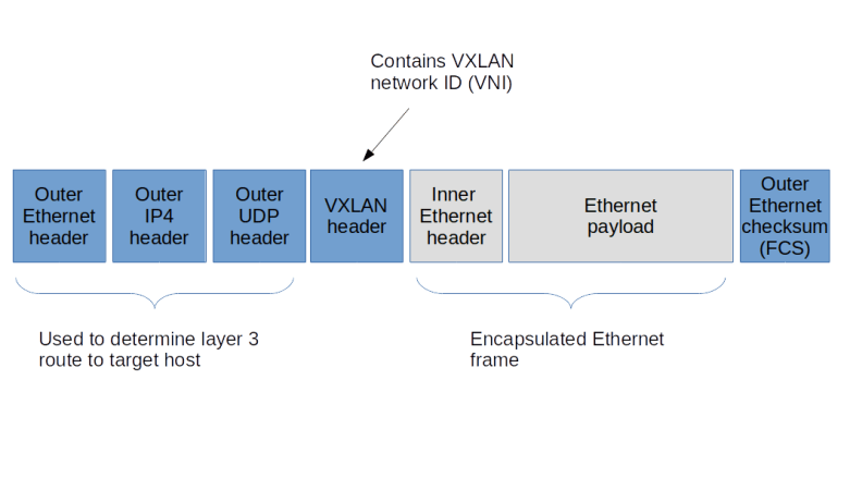
To be able to isolate different VXLANs from each other, a 24 bit VXLAN network identifier (VNI) is used. The implementation needs to make sure that Ethernet frames are only delivered within the same VNI, thus isolating the different VXLAN networks from each other. A host that is able to provide VXLAN devices and to participate in the exchange of UDP packets is called a VXLAN tunnel endpoint (VTEP). Thus to send an Ethernet frame over VXLAN, a VTEP needs to
- Add a VXLAN header that contains the VNI, so that the receiving VTEP can make sure that the frame is only delivered within the correct VNI
- Pass the resulting data as payload to the own IP stack, which will add a UDP, IP and Ethernet header to be able to transmit the frame over an existing layer 2 network
To be able to locate the UDP target address to which we have to send an encapsulated Ethernet frame, each VTEP needs to maintain a table containing mapping between the IP addresses of other VTEPs and the corresponding MAC addresses. A VTEP typically learns how to populate this table and uses IP multicast to ask other VTEPS to resolve unknown MAC addresses, similar to the ARP protocol.
When VXLAN is used, there are a few points that should be kept in mind. First, we do of course add quite a bit of overhead. For every Ethernet frame that is being exchanged, we add a second Ethernet header, an IP header and a UDP header, plus the processing time it takes on the host to travel the networking stack up and down once more. In addition, there is a problem with the MTU (maximum transfer unit) configured for the VXLAN endpoints. As the Ethernet frames on the physical network are longer than the Ethernet frames on the overlay network (as we need the additional headers), we will have to increase the MTU on the physical network to account for this in order to avoid unnecessary fragmentation. Also, using VXLAN implies that your Ethernet frames flow in clear text over the IP connection, so if you want to use VXLAN across unsecure network areas, then you should use some form of encryption like IPSec.
Lab 9: setting up a point-to-point VXLAN connection
To see this in action, let us first implement a very basic scenario. Assume that we have two hosts (virtual machines provided by VirtualBox in our case) that are part of the same layer 3 network. On each host, we ask the Linux kernel to create a virtual device of type VXLAN. To this virtual device, we can assign IP addresses as usual. Any Ethernet frames sent to the device will be encapsulated using the VXLAN protocol and will be sent to the peer, where the Linux kernel will strip off the outer header and re-inject the Ethernet frame. So the Linux kernel acts as a VTEP on both sides.

Again, I have automated the setup using Vagrant and Ansible. To run the example, simply enter the following commands
git clone https://github.com/christianb93/networking-samples
cd networking-samples/lab9
vagrant up
To inspect the setup, let us first SSH into boxA. If you run ifconfig -a, you will in fact see a new device called vxlan0. This device has been created and configured by our Ansible script using the following commands.
ip link add type vxlan id 100 remote 192.168.50.5 dstport 4789 dev enp0s8
ip addr add 192.168.60.4/24 dev vxlan0
ip link set vxlan0 up
The first command creates the device, specifying the VNI 100, the IP address of the peer, the port number to use for the UDP connection (we use the port number defined in RFC 7348) and the physical device to be used for the transmission. The second and third command then assign an IP address and bring the device up.
When you run netstat -a on boxA, you will also find that a UDP socket has been created on port 4789, this socket is ready to accept UDP packets from the peer carrying encapsulated Ethernet frames. The setup on boxB is similar, using of course a different IP address.
Let us now try to exchange traffic and to display the packets that go forth and back. For that purpose, open an SSH session on boxB as well and start a tcdump session listening on vxlan0.
sudo tcpdump -e -i vxlan0
You will a sequence of ARP and IPv4 packets, with the source and target MAC addresses matching the MAC addresses of the vxlan0 devices on the respective hosts. Thus the device acts like an ordinary Ethernet device, as expected.
Now let us change the setup and start to dump traffic on the underlying physical interface.
sudo tcpdump -e -i enp0s8
When you now repeat the ping, you will see that the packets arriving at the physical interface are UDP packets. In fact, tcpdump properly recognizes these frames as VXLAN frames and also prints the inner headers. We see that the outer Ethernet headers contain the MAC addresses of the underlying network interfaces of boxA and boxB, whereas the inner headers contain the MAC addresses of the vxlan0 devices.
Lab 10: VXLAN and IP multicasting
So far, we have used a direct point-to-point connection between the two hosts involved in the VXLAN network. In reality, of course, things are more complicated. Suppose, for instance, that we have three hosts representing VTEP endpoints. If an Ethernet frame on one of the hosts reaches the VXLAN interface, the kernel needs to determine to which of the other hosts the resulting UDP packet should be sent.
Of course, we could simply broadcast the packet to all hosts on the IP network, using a broadcast, but this would be terribly inefficient. Instead, VXLAN uses IP multicast functionality. To this end, the administrator setting up VXLAN needs to associate an IP multicast address with each VNI. A VTEP will then join this group and will use the IP multicast address for all traffic that needs to go to one or more Ethernet destinations. In a local network, you want to use one of the “private” IP multicast groups in the range 239.0.0.0 – 239.255.255.255 reserved by RFC 2365, for instance within the local scope 239.255.0.0/16.
To study this, I have created lab 10 which establishes a scenario in which three hosts serve as VTEP to span a VXLAN with VNI 100. As always, grab the code from GitHub, cd into the directory lab10 and run vagrant up to start the example.

The setup is very similar to the setup for the point-to-point connection above, with the difference that when bringing up the VXLAN device, we have removed the remote parameter and replaced it by the group parameter to tie the VNI to the multicast group.
ip link \
   add type vxlan \
   id 100 \
   group 239.255.0.1 \
   ttl 5 \
   dstport 4789 \
   dev enp0s8
Note the parameter TTL which defines the initial TTL that will be set on the UDP packets sent out by the VTEP. When I tried this setup first, I did not set the TTL, resulting in the default of one. With this setup, however, ARP requests were not answered by the target host, and I had to increase the TTL by adding the additional parameter.
Let us test this setup. Open SSH connections to the boxA and boxB. First, we can use ip maddr show enp0s8 to verify that on both machines, the interface enp0s8 has joined the multicast group 239.255.0.1 that we specified when bringing up the VXLAN. Then, start a tcpdump session on enp0s8 on boxC and ping the VXLAN IP address 192.168.60.5 of boxB from boxA. As this is the first time we establish this connection, the Ethernet device should emit an ARP request. This ARP request is encapsulated and sent out as an IP multicast with IP target address 239.255.0.1. In tcpdump, the corresponding output (again displaying the outer and inner headers) looks as follows.
06:30:44.255166 08:00:27:fe:3b:d0 (oui Unknown) > 01:00:5e:7f:00:01 (oui Unknown), ethertype IPv4 (0x0800), length 92: 192.168.50.4.57732 > 239.255.0.1.4789: VXLAN, flags [I] (0x08), vni 100
b6:02:f0:c8:15:85 (oui Unknown) > Broadcast, ethertype ARP (0x0806), length 42: Request who-has 192.168.60.5 tell 192.168.60.4, length 28
We can clearly see that the outer IP header has the multicast IP address as target address, and that the inner frame is an ARP request, looking to resolve the IP address of the VXLAN device on boxB.
The multicast mechanism is used to initially discover the mapping of IP addresses to Ethernet addresses. However, this is typically only required once, because the VTEP is able to learn this mapping by storing it in a forwarding database (FDB). To see this mapping, switch to boxA and run
bridge fdb show dev vxlan0
In the output, you should be able to locate the Ethernet address of the VXLAN device on boxC, being mapped to the IP address of boxC on the underlying network, i.e. 192.168.50.6.
Other overlay solutions
In this post, we have studied overlay networks based on VXLAN in some detail. However, VXLAN is not the only available overlay protocol. We just mention two alternative solutions without going into details.
First, there is GRE (Generic Routing Encapsulation). which is defined in RFC 2784. GRE is a generic protocol to encapsulate packets within other packets. It defines a GRE header, which is put between the headers of the outer protocol and the payload, similar to the VXLAN header. Other than VXLAN, GRE allows different protocols both as payload protocols and as delivery (outer) protocols. Linux supports both IP over IP tunneling using GRE, using the device type gre for IP-over-IP tunnels and the device type gretap for Ethernet-over-IP tunneling.
Then, there is GENEVE, which is an attempt to standardize encapsulation protocols. It is very similar to VXLAN, tunneling Ethernet frames over UDP, but defines a header with optional fields to allow for future extensions.
And finally, Linux offers a few additional tunneling protocols like the IPIP module for tunneling of IP over IP traffic or SIT to tunnel IPv6 over IPv4 which have been present in the kernel for some time and predate some of the standards just discussed.
In this and the previous posts, we have mainly used Linux kernel technology to realize network virtualization. However, there are other options available. In the next post, I will start to explore Open vSwitch (OVS), which is an open-source software defined switching solution.

1 Comment