
In this post, we will learn how to set up VXLAN overlay networks as tenant networks in Neutron and explore the resulting configuration on our compute nodes.
Tenant networks
The networks that we have used so far have been provider networks – they have been created by an administrator, specifying the link to the physical network resource (physical network, VLAN ID) manually. As already indicated in our introduction to Neutron, OpenStack also allows us to create tenant networks, i.e. networks that a tenant, using a non-privileged user, can create using either the CLI or the GUI.
To make this work, Neutron needs to understand which resources, i.e. VLAN IDs in the case of VLANs or VXLAN IDs in the case of VXLANs, it can use when a tenant requests the creation of a network without getting in conflict with the physical network infrastructure. To achieve this, the configuration of the ML2 plugin allows us to specify ranges for VLANs and VXLANs which act as pools from which Neutron can allocate resources to tenant networks. In the case of VLANs, these ranges can be specified in the item network_vlan_ranges that we have already seen. Instead of just specifying the name of a physical network, we could use an expression like
physnet:100:200
to tell Neutron that the VLAN ids between 100 and 200 can be freely allocated for tenant networks. A similar range can be specified for VXLANs, here the configuration item is called vni_ranges. In addition, the ML2 configuration contains the item tenant_network_types which is an ordered list of network types which are offered as tenant networks.
When a user requests the creation of a tenant network, Neutron will go through this list in the specified order. For each network type, it will try to find a free segmentation ID. The first segmentation ID found determines the type of the network. If, for instance, all configured VLAN ids are already in use, but there is still a free VXLAN id, the tenant network will be created as a VXLAN network.
Setting up VXLAN networks in Neutron
After this theoretical discussion, let us now configure our playground to offer VXLAN networks as tenant networks. Here are the configuration changes that we need to enable VXLAN tenant networks.
- add vxlan to the list type_drivers in the ML plugin configuration file ml2_conf.ini so that VXLAN networks are enabled
- add vxlan to tenant_network_types in the same file
- navigate to the ml2_type_vxlan section and edit vni_ranges to specify VXLAN IDs available for tenant networks
- Set the local_ip in the configuration of OVS agent, which is the ID on which the agent will listen for VXLAN connections. Here we use the IP address of the management network (which is something you would probably not do in a real world situation as it is preferred to use separate network interfaces for management and VM traffic, but in our setup, the interface connected to the provider network is unnumbered)
- In the same file, add vxlan to the key tunnel_types
- In the Horizon configuration, add vxlan to the item horizon_supported_network_types
Instead of doing all this manually, you can of course once more use one of the Labs that I have created for you. To do this, run
git clone https://github.com/christianb93/openstack-labs
cd Lab9
vagrant up
ansible-playbook -i hosts.ini site.yaml
ansible-playbook -i hosts.ini demo_base.yaml
Note that the second playbook that we run will create a demo project and a demo user as in our previous projects as well as the m1.nano flavor. This playbook will also modify the default security groups to allow incoming ICMP and SSH traffic.
Let us now inspect the state of the compute nodes by logging into the compute node and executing the usual commands to check our network configuration.
vagrant ssh compute1
ifconfig -a
sudo ovs-vsctl show
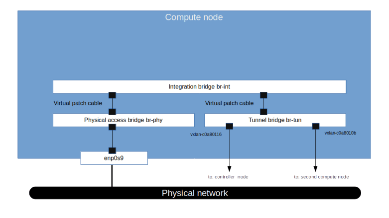
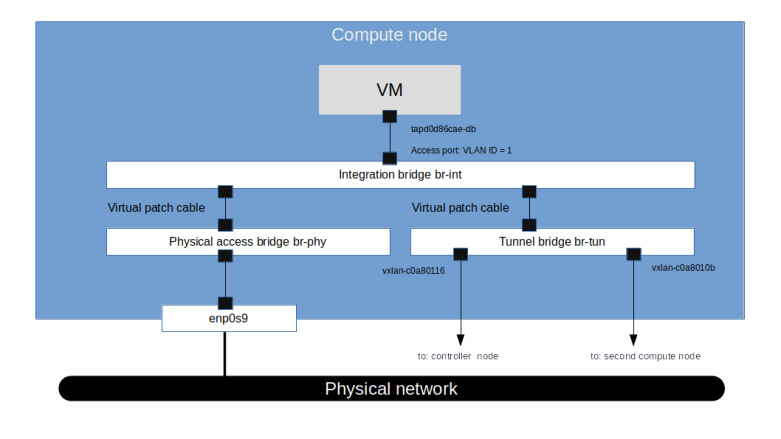
The first major difference that we see compared to the previous setup with a pure VLAN based network separation is that an additional OVS bridge has been created by Neutron called the tunnel bridge br-tun. This bridge is connected to the integration bridge by a virtual patch cable. Attached to this bridge, there are two VXLAN peer-to-peer ports that connect the tunnel bridge on the compute node compute1 to the tunnel bridges on the second compute node and the controller node.
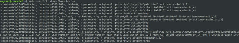
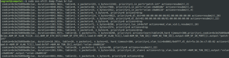
Let us now inspect the flows defined for the tunnel bridge. At this point in time, with no virtual machines created, the rules are rather simple – all packets are currently dropped.
Let us now verify that, as promised, a non-admin user can use the Horizon GUI to create virtual networks. So let us log into the Horizon GUI (reachable from the lab host via http://192.168.1.11/horizon as the demo user (use the demo password from /.os_credentials/credentials.yaml) and navigate to the “Networks” page. Now click on “Create Network” at the top right corner of the page. Fill in all three tabs to create a network with the following attributes.
- Name: vxlan-network
- Subnet name: vxlan-subnet
- Network address: 172.18.0.0/24
- Gateway IP: 172.18.0.1
- Allocation Pools: 172.18.0.2,172.18.0.10 (make sure that there is no space after the comma separating the start and end address of the allocation pool)
It is interesting to note that the GUI does not ask us to specify a network type. This is in line with our discussion above on the mechanism that Neutron uses to assign tenant networks – we have only specified one tenant network type, namely VXLAN, and even if we had specified more than one, Neutron would pick the next available combination of segmentation ID and type for us automatically.
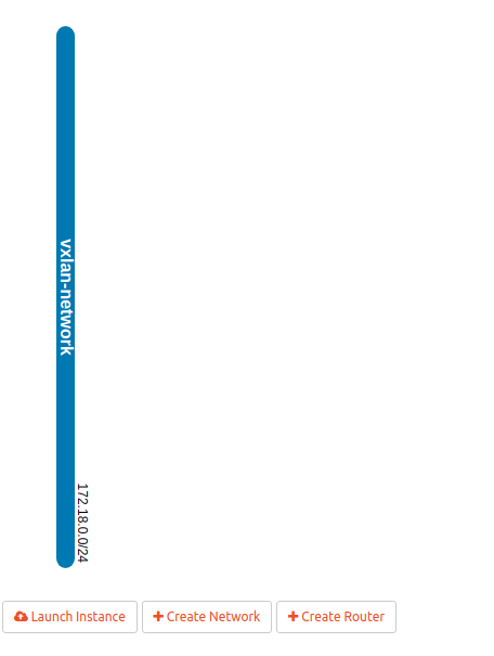
If everything worked, you should now be able to navigate to the “Network topology” page and see the following, very simple network layout.
Now use the button “Launch Instance” to create two instances demo-instance-1 and demo-instance-2 attached to the VXLAN network that we have just created. When we now navigate back to the network topology overview, the image should look similar to the one below.
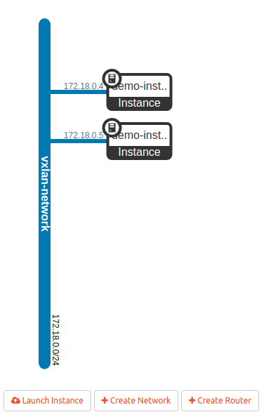
Using the noVNC console, you should now be able to log into your instances and ping the first instance from the second one and the other way around. When we now re-investigate the network setup on the compute node, we see that a few things have changed.
First, as you would probably guess from what we have learned in the previous post, an additional tap port has been created which connects the integration bridge to the virtual machine instance on the compute node. This port is an access port with VLAN tag 1, which is again the local VLAN ID.
The second change that we find is that additional rules have been created on the tunnel bridge.Ethernet unicast traffic coming from the integration bridge is processed by table 20. In this table, we have one rule for each peer which directs traffic tagged with VLAN ID 1 for this peer to the respective VXLAN port. Note that the MAC destination address used here is the address of the tap port of the respective other VM. Outgoing Ethernet multicast traffic with VLAN ID 1 is copied to all VXLAN ports (“flooding rule”). Traffic with unknown VLAN IDs is dropped.
For ingress traffic, the VXLAN ID is mapped to VLAN IDs in table 4 and the packets are forwarded to table 10. In this table, we find a learning rule that will make sure that MAC addresses from which traffic is received are considered as targets in table 20. Typically, the packet triggering this learning rule is an ARP reply or an ARP request, so that the table is populated automatically when two machines establish an IP based communication. Then the packet is forwarded to the integration bridge.
At this point, we have two instances which can talk to each other, but there is still no way to connect these instances to the outside world. To do this, let us now add an external network and a router.
The external network will be a flat network, i.e. a provider network, and therefore needs to be added as admin user. We do this using the CLI on the controller node.
vagrant ssh controller
source admin-openrc
openstack network create \
  --share \
  --external \
  --provider-network-type flat \
  --provider-physical-network physnet \
  flat-network
openstack subnet create \
  --dhcp  \
  --subnet-range 172.16.0.0/24 \
  --network flat-network \
  --allocation-pool start=172.16.0.2,end=172.16.0.10 \
  flat-subnet
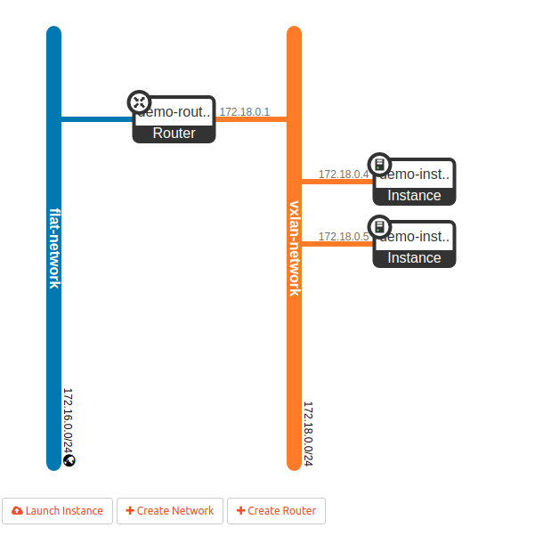
Back in the Horizon GUI (where we are logged in as the user demo), let us now create a router demo-router with the flat network that we just created as the external network. When you inspect the newly created router in the GUI, you will find that Neutron has assigned one of the IP addresses on the flat network to the external interface of the router. On the “Interfaces” tab, we can now create an internal interface connected to the VXLAN network. When we verify our work so far in the network topology overview, the displayed image should look similar to the one below.
Finally, to be able to reach our instances from the flat network (and from the lab host), we need to assign a floating IP. We will create it using the CLI as the demo user.
vagrant ssh controller
source demo-openrc
openstack floating ip create \
  --subnet flat-subnet \
  flat-network
Now switch back to the GUI and navigate to the compute instance to which you want to attach the floating IP, say demo-instance-1. From the instance overview page, select “Associate floating IP”, pick the IP address of the floating IP that we have just created and complete the association. At this point, you should be able to ping your instance and SSH into it from the lab host.
Concluding remarks
Before closing this post, let us quickly discuss several aspects of VXLAN networks in OpenStack that we have not yet touched upon.
First, it is worth mentioning that the MTU settings turn out to be an issue that comes up frequently when working with VXLANs. Recall that VXLAN technology encapsulates Ethernet frames in UDP packets. This implies a certain overhead – to a given Ethernet frame, we need to add a VXLAN header, a UDP header, an IP header and another Ethernet header. This overhead increases the size of a packet compared to the size of the payload.
Now, in an Ethernet network, every interface has an MTU (minimum transmission unit) which defines the maximum payload size of a frame which can be processed by this interface without fragmentation. A typical MTU for Ethernet is 1500 bytes, which (adding 14 bytes for the Ethernet header and 4 bytes for the checksum) corresponds to an Ethernet frame of 1518 bytes. However, if the MTU of the physical device on the host used to transmit the VXLAN packets is 1500 bytes, the MTU available to the virtual device is smaller, as the packet transmitted by the physical device is composed of the packet transmitted by the virtual device plus the overhead.
As discussed in RFC 4459, there are several possible solutions for this issue which essentially boil down to two alternatives. First, we could of course simply allow fragmentation so that packets exceeding the MTU are fragmented, either by the encapsulator (i.e. fragment the outer packet) or by the virtual interface (i.e. fragment the inner packet). Second, we could adjust the MTU of the underlying network infrastructure, for instance by jusing Jumbo frames with a size of 9000 bytes. The long and interesting discussion of the pros and cons of both approaches in the RFC comes to the conclusion that no clean and easy solution for this problem exists. The approach that OpenStack takes by default is to reduce the MTU of the virtual network interfaces (see the comments of the parameter global_physnet_mtu in the Neutron configuration file). In addition, the ML2 plugin can also be configured with specific MTUs for physical devices and a path MTU, see this page for a short discussion of the options.
The second challenge that the usage of VXLAN can create is the overhead generated by broadcast traffic. As OVS does not support the use of VXLAN in combination with multicast IP groups, Neutron needs to handle broadcast and multicast traffic differently. We have already seen that Neutron will install OpenFlow rules on the tunnel bridge (if you want to know all nitty-gritty details, the method tunnel_sync in the OVS agent is a good starting point), which implies that all broadcast traffic like ARP requests go to all nodes, even those on which no VMs in the same virtual network are hosted (and, as remarked above, the reply typically creates a learned OpenFlow rule used for further communication).
To avoid the unnecessary overhead of this type of broadcast traffic, the L2 population driver was introduced. This driver uses a proxy ARP mechanism to intercept ARP requests coming from the virtual machines on the bridge. The ARP requests are then answered locally, using an OpenFlow rule, and the request never leaves the local machine. As therefore the ARP reply can no longer be used to learn the MAC addresses of the peers, forwarding rules are created directly by the agent to send traffic to the correct VXLAN endpoint (see here for an entry point into the code).

1 Comment