
In this post, which is part of our series on OpenStack, we will start to investigate OpenStack Neutron – the OpenStack component which provides virtual networking services.
Network types and some terms
Before getting into the actual Neutron architecture, let us try to understand how Neutron provides virtual networking capabilities to compute instances. First, it is important to understand that in contrast to some container networking technologies like Calico, Neutron provides actual layer 2 connectivity to compute instances. Networks in Neutron are layer 2 networks, and if two compute instances are assigned to the same virtual network, they are connected to an actual virtual Ethernet segment and can reach each other on the Ethernet level.
What technologies do we have available to realize this? In a first step, let us focus on connecting two different virtual machines running on the same host. So assume that we are given two virtual machines, call them VM1 and VM2, on the same physical compute node. Our hypervisor will attach a virtual interface (VIF) to each of these virtual machines. In a physical network, you would simply connect these two interfaces to ports of a switch to connect the instances. In our case, we can use a virtual switch / bridge to achieve this.
OpenStack is able to leverage several bridging technologies. First, OpenStack can of course use the Linux bridge driver to build and configure virtual switches. In addition, Neutron comes with a driver that uses Open vSwitch (OVS). Throughout this series, I will focus on the use of OVS as a virtual switch.
So, to connect the VMs running on the same host, Neutron could use (and it actually does) an OVS bridge to which the virtual machine networking interfaces are attached. This bridge is called the integration bridge. We will see later that, as in a typical physical network, this bridge is also connected to a DHCP agent, routers and so forth.
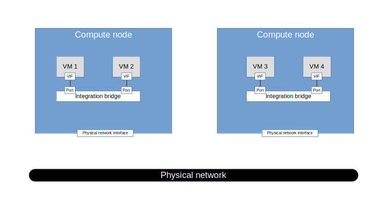
But even for the simple case of VMs on the same host, we are not yet done. In reality, to operate a cloud at scale, you will need some approach to isolate networks. If, for instance, the two VMs belong to different tenants, you do not want them to be on the same network. To do this, Neutron uses VLANs. So the ports connecting the integration bridge to the individual VMs are tagged, and there is one VLAN for each Neutron network.
This networking type is called a local network in Neutron. It is possible to set up Neutron to only use this type of network, but in reality, this is of course not really useful. Instead, we need to move on and connect the VMs that are attached to the same network on different hosts. To do this, we will have to use some virtual networking technology to connect the integration bridges on the different hosts.
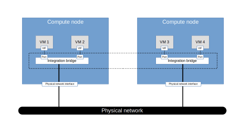
At this point, the above diagram is – on purpose – a bit vague, as there are several technologies available to achieve this (and I am cheating a bit and ignoring the fact that the integration bridge is not actually connected to a physical network interface but to a second bridge which in turn is connected to the network interface). First, we could simply connect each integration bridge to a physical network device which in turn is connected to the physical network. With this setup, called a flat network in Neutron, all virtual machines are effectively connected to the same Ethernet segment. Consequently, there can only be one flat network per deployment.
The second option we have is to use VLANs to partition the physical network according to the virtual networks that we wish to establish. In this approach, Neutron would assign a global VLAN ID to each virtual network (which in general is different from the VLAN ID used on the integration bridge) and tag the traffic within each virtual network with the corresponding VLAN ID before handing it over to the physical network infrastructure.
Finally, we could use tunnels to connect the integration bridges across the hosts. Neutron supports the most commonly used tunneling protocols (VXLAN, GRE, Geneve).
Regardless of the network type used, Neutron networks can be external or internal. External networks are networks that allow for connectivity to networks outside of the OpenStack deployment, like the Internet, whereas internal networks are isolated. Technically, Neutron does not really know whether a network has connectivity to the outside world, therefore “external network” is essentially a flag attached to a network which becomes relevant when we discuss IP routers in a later post.
Finally, Neutron deployment guides often use the terms provider network and tenant networks. To understand what this means, suppose you wanted to establish a network using e.g. VLAN tagging for separation. When defining this network, you would have to assign a VLAN tag to this virtual network. Of course, you need to make sure that there are no collisions with other Neutron networks or other reserved VLAN IDs on the physical networks. To achieve this, there are two options.
First, an administrator who has a certain understanding of the underlying physical network structure could determine an available VLAN ID and assign it. This implies that an administrator needs to define the network, and thus, from the point of view of a tenant using the platform, the network is created by the platform provider. Therefore, these networks are called provider networks.
Alternatively, an administrator could, initially, when installing Neutron, define a pool of available VLAN IDs. Using this pool, Neutron would then be able to automatically assing a VLAN ID when a tenant uses, say, the Horizon GUI to create a network. With this mechanism in place, tenants can define their own networks without having to rely on an administrator. Therefore, these networks are called tenant networks.
Neutron architecture
Armed with this basic understanding of how Neutron realizes virtual networks, let us now take a closer look at the architecture of Neutron.
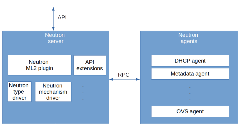
The diagram above displays a very rough high-level overview of the components that make up Neutron. First, there is the Neutron server on the left hand side that provides the Neutron API endpoint. Then, there are the components that provide the actual functionality behind the API. The core functionality of Neutron is provided by a plugin called the core plugin. At the time of writing, there is one plugin – the ML2 plugin – which is provided by the Neutron team, but there are also other plugins available which are provided by third parties, like the Contrail plugin. Technically, a plugin is simply a Python class implementing the methods of the NeutronPluginBaseV2 class.
The Neutron API can be extended by API extensions. These extensions (which are again Python classes which are stored in a special directory and loaded upon startup) can be action extensions (which provide additional actions on existing resources), resource extensions (which provide new API resources) or request extensions that add new fields to existing requests.
Now let us take a closer look at the ML2 plugin. This plugin again utilizes pluggable modules called drivers. There are two types of drivers. First, there are type drivers which provide functionality for a specific network type, like a flat network, a VXLAN network, a VLAN network and so forth. Second, there are mechanism drivers that contain the logic specific to an implementation, like OVS or Linux bridging. Typically, the mechanism driver will in turn communicate with an L2 agent like the OVS agent running on the compute nodes.
On the right hand side of the diagram, we see several agents. Neutron comes with agents for additional functionality like DHCP, a metadata server or IP routing. In addition, there are agents running on the compute node to manipulate the network stack there, like the OVS agent or the Linux bridging agent, which correspond to the chosen mechanism drivers.
Basic Neutron objects
To close this post, let us take a closer look at same of the objects that Neutron manages. First, there are networks. As mentioned above, these are virtual layer 2 networks to which a virtual machine can attach. The point where the machine attaches is called a port. Each port belongs to a network and has a MAC address. A port contains a reference to the device to which it is attached. This can be a Nova managed instance, but also be another network device like a DHCP agent or a router. In addition, an IP address can be assigned to a port, either directly when the port is created (this is often called a fixed IP address) or dynamically.
In addition to layer 2 networks, Neutron has the concept of a subnet. A subnet is attached to a network and describes an IP network on top of this Ethernet network. Thus, a subnet has a CIDR and a gateway IP address.
Of course, this list is far from complete – there are routers, floating IP addresses, DNS servers and so forth. We will touch upon some of these objects in later posts in this series. In the next post, we will learn more about the components making up Neutron and how they are installed.

2 Comments