
So far, we have looked at states of a quantum computer and expressed these states in terms of qubits. However, just having a static state is of very limited use – to perform actual computations, we of course have to change our state over time.
In quantum mechanics, state changes are described by unitary transformations on the Hilbert space describing our quantum system. In analogy with a classical computer, where signals traverse logical gates and are manipulated by these gates to perform calculations, these transformations are called quantum gates. However, please keep in mind that in most actual implementations of quantum computers, these gates are not circuits or building blocks in the classical sense through which the qubits somehow travel. Instead, the qubits are mostly at a fixed point in space, and a gate is applied to a quantum state by manipulating the system, using for instance laser beams or magnetic fields.
One qubit quantum gates
Let us again start with the case of a single qubit, i.e. with a two-dimensional Hilbert space. With respect to the standard basis 
As a first example, let us consider the matrix
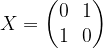
Obviously, this operator exchanges the states 


and

A second commonly used operator is the operator conventionally denoted by Z and given by
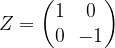
Clearly, the eigenvalues of this operator are again +1 and -1, but this time, an eigenbasis is given by the standard basis. On a superposition, this operator changes the relative phase, so it is often called the phase change or phase flip operator. A reader with a background in quantum physics might recognize these two operators as being two of the three Pauli operators. They all have determinant -1, trace 0, are hermitian and unitary and their square is the identity operator.
The eigenstates of X form an orthogonal basis, and hence they can be mapped into the standard basis by applying a unitary transformation. The corresponding operator is the Hadamard operator given by

As we can see, 


that changes the relative phase to an imaginary value transforms between the eigenstates of X and the third Pauli operator. The two gates H and S are sometimes referred to as Clifford gates (they have the property that conjugation with them takes the set of Pauli matrices onto itself).
Similar to classical circuits, quantum gates and combinations of quantum gates are often represented graphically. A single quantum gate is represented by a box, with incoming qubits (i.e. the qubits on which the transformation acts) being indicated by incoming lines on the left and the result being represented by outgoing lines on the right.
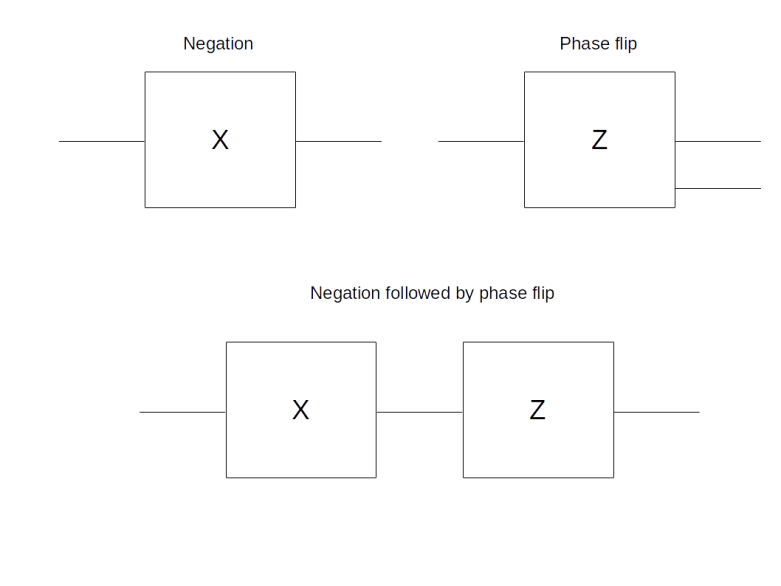
In the example above, the first line shows two individual gates, the negation and the phase flip operator. The second line graphically represents the process of applying to a single qubit first the negation and then the phase flip. Of course, the resulting matrix is given by the matrix product
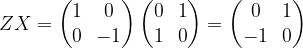
Note that the order of the matrix product is reversed, as we first apply X and then Z, reading the diagram from the left to the right which is the usual convention. We also note that this matrix is sometimes called Y, whereas other authors use Y to denote -i times this matrix. We stick to the convention to use Y for the product ZX given above.
Multi-qubit gates – the CNOT and other controlled gates
Having discussed some of the fundamental quantum gates acting on one qubit, let us now turn again to multi-qubit systems. Of course, we can always create transformations on a multi-qubit system by acting on each qubit individually with a given unitary operator, i.e. by forming the tensor product of operators. Graphically, this would be represented as gates placed below each other, each acting only on one line, i.e. qubit. However, things get more interesting when we use gates that are actually combining multiple qubits to model some non-trivial logic.
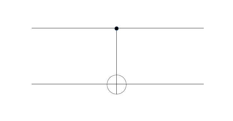
As an example, let us consider a gate acting on two qubits that is commonly known as the CNOT gate. To express this gate as a matrix, we have to agree on an order of the basis of the tensor product, and is is natural to use the order 

To understand what this operator is actually doing, let us see how it acts on a basis. Clearly, it maps 


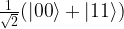
An interesting property of the CNOT gate is that it takes separable states to entangled states. Let us for instance compute the action of the CNOT gate on the state 

from which we can read off that

which, up to a normalization factor, is an entangled Bell state. Thus we can use the CNOT gate to create entangled states. We also see that, other than the symbol does suggest, the operator does act on the control bit as well.
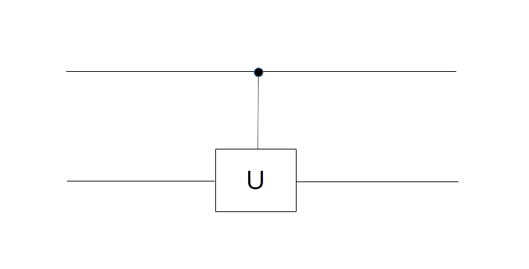
The notation of a controlled NOT gate can be extended to cover more general gates. Given any unitary one-qubit transformation U, we can in fact consider the two-qubit operator that applies the identify to the second qubit if the first qubit (the control bit) is
To get used to the graphical notation, let us take a look at the following two-qubit circuit and try to understand what it does to the standard basis.
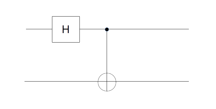
There are several approaches to figure out what this circuit is doing. First, we can look at its action on each of the basis vectors. Let us do this for the basis vector 

to the state

The second part of the circuit, the CNOT gate, then maps 

which again is an entangled Bell state. We could now proceed like this for the other basis vectors. Alternatively, we can find the answer by multiplying out the matrices and will arrive at the same result.
Universal quantum gates
In classical computing, a general circuit with n input bits and one output bit can be described by a function taking 

Unfortunately, this does not work in the quantum world. The problem is that the group of unitary matrices is not discrete, but continuous, and thus we can never hope to be able to generate it fully using only a finite number of different gates. However, something very similar is true – every gate can be approximated by combining gates from a small, universal set.
This result is typically presented and derived in two steps (see for instance [1], chapter 3). First, one shows that every unitary transformation of an n-qubit system can be reduced to a combination of single qubit operations (tensored with the identity) and CNOT gates. This is still exact, i.e. no approximation takes place (for the mathematically inclined reader, this might ring a bell – in fact, there is a relation to Cartan decompositions of unitary matrices, see for instance [3] for a discussion).
Then, in a second step, one shows that every single qubit transformation can be approximated arbitrarily close by products of a finite universal set of gates – this is known as the Solovay-Kitaev theorem. It turns out (see for instance [4]) that a possible choice for such a universal set consists of the Hadamard gate H, the phase flip gate Z and only one additional gate

which is confusingly sometimes called the 
Finally, we mention that a three-qubit gate that is often used to construct universal sets of quantum gates is the Toffoli gate. This is like a CNOT gate, except that it has two control bits and the target bit is only flipped if both control bits are ON. It is known that the set consisting of the Toffoli gate and the Hadamard gate only is already universal in a similar sense (see this paper by D. Aharonov for a short proof of this result that goes back to Y. Shi). This result is of a certain importance because one can also show that the classical version of the Toffoli gate alone is sufficient to implement (a reversible version of) any classical circuit. Thus we do not only see that any computation that can be done by a classical circuit can also be done by a quantum circuit, but also that without the Hadamard gate, quantum computing would not be more powerful than classical computing.
This closes our short discussion of elementary quantum gates. In the next few posts, we will start to combine quantum gates into quantum algorithms to perform actual computations. Stay tuned!
References
1. G. Benenti, G. Casati, G. Strini, Principles of Quantum Computation and Information, Volume 1, World Scientific
2. E. Rieffel, W. Polak, Quantum computing – a gentle introduction, MIT Press
3. N. Khaneja, S.J. Glaser, Cartan Decomposition of SU(2 n ), Constructive Controllability of Spin Systems and Universal Quantum Computing, arXiv:quant-ph/0010100v1
4. P. Boykin, T. Mor, M. Pulver, V. Roychowdhury, F. Vatan, A new universal and fault-tolerant quantum basis
5. D. Aharonov,A Simple Proof that Toffoli and Hadamard are Quantum Universal, arXiv:quant-ph/0301040

4 Comments