
In our discussion of the IP protocol, the reader might have noticed that there are many desirable features that the IP protocol does not have. Suppose for instance that we are building an application that needs to transmit data in a stream oriented way – this could be a video, an MP3 file or a data transfer modelling a conversation. When we simply split our data into IP packets and send them directly via IP, there are many issues that we have to solve. IP does not guarantee us that packets even arrive, so we will have to deal with lost packets and build some acknowledgement and retransmission mechanism. Even if the packets arrive, the order in which they arrive is not guaranteed – different packets could be routed along different paths and arrive in reversed order. So we need a mechanism to encode the order and reassemble them at the destination in the right order. If the receiver needs some time to process the packets, we might want to control and dynamically adjust the rate of transmission. And finally, IP only assigns one address to a host (more precisely, a network card), so our transmission might conflict with other applications running on the same host and we need a way to deal with this.
Fortunately, the internet protocol stack offers a protocol sitting on top of IP and offering all this – the transmission control protocol, commonly known as TCP (there are other protocols on top of IP like ICMP that we have already seen in action and UDP, but we will focus on TCP in this post).
The main properties of the TCP protocol are:
- It is reliable – the transmission of each piece of data is guaranteed by acknowledgement and retransmission capabilities of the protocol
- It is connection oriented. When TCP is used, a connection with endpoints on both hosts is established first through a handshake procedure. Once the connection is established, both parties can write and read from the connection at the same time until all the data is transferred, then the connection is closed again. A connection endpoint (a socket) is identified using the IP address and an additional number, called the port number so that different connections originating or ending at the same host can operate independently.
- It is stream oriented. An application dealing with TCP does not have to know anything about packet sizes, fragmentation, reassembly, MTUs and so forth – it just writes data sequentially into a socket or reads data sequentially from a socket. Most operating systems make writing to and reading from a socket as easy as dealing with a file. The protocol makes sure that the bytes that are written into one of the endpoints arrive at the second endpoint completely and in the same order.
- And finally, TCP offers congestion control, i.e. the protocol automatically throttles the transmission speed if it realizes congestion.
TCP is a rather complicated protocol, and it is hopeless to cover it entirely in one post. Instead, we will look at a few of those points in more detail in the following sections.
Connection endpoints and ports
The TCP protocol has first been standardized in RFC 793 (and since then adapted and enhanced by many other RFCs). This is were we also find the structure of a TCP header (see section 3.1 of the document). The first two 16 bit words in the header are called source port and destination port.
Together with the IP address, the port number defines the full address relevant for a TCP connection. The combination of an IP address with a port number is sometimes called a socket in the RFC and is conventionally denoted by prefixing the port number by the IP address followed by a colon, for instance 192.168.178.1:23 for the port number 23 on the host with IP address 192.168.178.1. However, the port number does not simply supplement the IP address. Instead, TCP operates by building connections which are determined by the full endpoints – IP address and port numbers – on both sides.
Let us look at an example to explain this. Suppose you are running a web server on a host with IP address 10.0.2.20. Traditionally, a web server uses the port number 80.
Now suppose a first client connects to this web server. Let us assume that the client has the IP address 10.0.2.21 and that the operating system of the client decides to use the port number 3333 on the client to establish the connection (we will see below how exactly that works). When this connection is established, the web server will typically spawn off a separate thread to handle the communication with this client. So there is now one connection
10.0.2.21:3333 — 10.0.2.20:80
Now a second client might connect to the web server as well – of course we want this to be possible. If this client is running on a machine with IP address 10.0.2.22 and using port 3334, we obtain a second connection
10.0.2.22:3334 — 10.0.2.20:80
The situation is displayed in the image below.
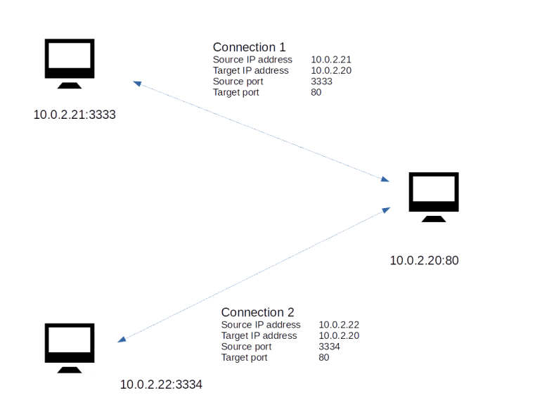
The web server will create a second thread that serves HTTP requests that are placed using this connection. Now the point is that even though both connections share the same endpoint 10.0.2.20:80, they operate completely independently! If a TCP message arrives at port 80 of the web server, the operating system will inspect the source IP address and source port number to match the message to an existing open connection. It will then forward the message to the thread responsible for this connection and to no other thread. Thus a connection, identified by the quadruple IP source address, IP target address, TCP source port, TCP target port, serves as a channel through which data can flow independently of any other connections, even if they share a common endpoint. This makes TCP compatible with the paradigm of multi-threaded servers.
Handshakes and the TCP state machine
The connection based approach of TCP obviously requires a mechanism to establish a connection when the communication between two nodes begins. It also implies that a TCP connection has a state. This is a major difference between TCP and pure IP. In the IP protocol, every packet is treated the same – the processing of a packet is independent of any previously received packet (which is strictly speaking only true if we ignore fragmentation for a moment). For TCP, this is not true. A TCP connection has a state and the processing triggered by the arrival of a packet is in the context of that state.
Thus, from a theoretical point of view, a TCP connection can be described as a state machine. There is a (finite) number of states, and the connection will move from one state to the next state triggered by events and packets.
The full TCP state machine is rather complicated, and we will not discuss all possible transitions. Rather, we will focus on those transitions that a connection goes through until it is fully established. A graphical representation of this part of the state machine would look as follows.
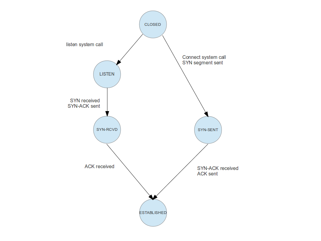
To understand this image, let us go through the transitions and events one by one for a real world example. Suppose you are pointing your web browser to a specific site on the WWW, say http://www.wordpress.com. Your browser will then use a DNS service to turn this human readable address into an IP address, say 192.0.78.13. At this IP address, a web server is listening on port 80.
When this web server was started, it did ask the operating system on which it is running to reserve port 80 for it, so that it is automatically owning all incoming connections on this port. Technically, this is done using an operating system call called listen on most operating systems. The operating system now knows that the web server is claiming this port. It will establish an object called a socket and move this socket into the state “listening”. Thus, the endpoint on the server side does actually go through the transition at the top left of the image above – transitioning a connection from “closed” (i.e. not existing in this case) to “listening”.
You can use the command netstat -tln -4 on a Linux machine to get a list of all listening TCP connections (for IPv4). Depending on your configuration, you might see sockets listening on the ports 53 (DNS server), 445 (Microsoft Windows shares/CIFS), 80 (Web server) or 139 (Microsoft NetBios).
Back to our example – what is the web browser doing? After having resolved the IP address, it will try to establish a connection to the IP address / port number 192.0.78.13:80. To do this, it will assemble and send a special TCP packet called a SYN packet. This packet does not contain any data, but a special bit (the SYN bit) in the TCP header of this packet is set. After sending this packet, the client side endpoint is now in the state “SYN-SENT”, i.e. the client part of the connection did traverse the path on the upper right of our image.
Once the SYN packet arrives at the server side, the server will reply with a packet that has the acknowledgement bit set in its header, to let the client know that the SYN packet was received. It will then move into the next state – SYN-RCVD. As the SYN packet does contain the IP address and port number of the client, the server know knows the other endpoint of the connection.
Next, the client will receive the acknowledgement of the SYN packet. It will then reply with another acknowledgement, this time to let in turn the server know that is has received the servers acknowledgement. It then moves into the final state “ESTABLISHED”. Once the server receives the acknowledgement, it will do the same. At this point, the connection between both parties is fully established and the exchange of data can start.
Acknowledgement and retransmission
During the initial handshake, we have already seen an important mechanisms – acknowledgements. TCP is a reliable protocol, i.e. it guarantees that packets are received by the other endpoint. To make this work, each endpoint acknowledges receipt of all packets so that the sender knows that the data has been received. If a packet is not acknowledged within a certain period of time, it is retransmitted.
To allow for a retransmission, a sender needs to maintain a buffer of data which has been sent, but not yet acknowledged by the peer, so that the data is still available for retransmission. When data is eventually acknowledged, the part of the buffer containing that data can be emptied.
Conversely, the receiver will typically also have to maintain a buffer, as the application might need some time to read and process all the data. This raises another complication – how can we make sure that this buffer does not overflow? What we need is a mechanism for the receiver to inform the sender about the size of the available buffer. This is called the send window.
To explain these concepts in a bit more detail, let us take a look at the following diagram.

What we see here is a short piece of a longer stream of data that needs to be transmitted. Each of the little boxes is one byte of data, and the number within the box contains the offset of this byte within the stream. This number is reflected during the transition by a sequence number which is part of the header of a TCP packet and marks where in the stream the data within the packet is located. When a receiver acknowledges receipt of a packet, it adds the sequence number of the acknowledged data to the acknowledgement message to avoid a dependency on the physical order of packets.
To keep track of the stream status, the sender maintains two numbers. The first number, usually abbreviated as SND_UNA, contains the smallest sequence number that has been sent, but not yet acknowledged by the peer. Thus every byte with a smaller offset has been acknowledged and can safely be removed from the buffer.
The pointer SND_NXT contains the next sequence number that can be sent. Thus the bytes between SND_UNA and SND_NXT have been sent, but not yet acknowledged, and the bytes after SND_NXT have been passed to the operating system on the sender side, but not yet transmitted. If additional data is passed to the operating system for sending, they are stored in the buffer and SND_NXT is incremented. When an acknowledgement is received, SND_UNA is incremented and older bytes are removed from the buffer.
An additional restriction is now given by the size of the send window. During the initial handshake, both endpoints exchange their desired send windows. The send window is then used as an upper bound for the number of bytes that are allowed to be in transit. Thus, in the example above, the bytes starting at offset 110 have already been handed over to the operating system for sending, but are in fact not yet ready to be sent as the send window of the peer is only 10 bytes.
All this sounds still comparatively simple, but can in fact become quite complicated. Complex algorithms have been defined in several RFCs to determine when exactly data is to be sent, what happens if an acknowledgement is not received, when exactly acknowledgements are sent, how the send rate is to be adapted to the capacity of the connection (congestion control) and so forth. Discussing all this would go far beyond the scope of this blog post. For those interested in the details, I recommend the two volumes of TCP/IP Illustrated by W. R. Stevens. If you prefer to look at source code, there are the implementations in the open source operating systems like FreeBSD and Linux. In addition, there is the implementation that I coded for my own toy operating system, especially the documentation of the networking stack and the source code of the TCP module.
