
In the last post in this series, we have covered the basics of the IP protocol – the layout of a network message and the process of fragmentation. However, there is one point which we have not yet discussed. Assume that an application or operating system has actually assembled a message and applied fragmentation so that the message is now ready to be sent. How would that actually work?
Routing in local networks: the ARP protocol
To understand the situation, assume for a moment that we are dealing with a very simple network topology. We are looking at a host which is part of a small network, and the host is directly connected to the same Ethernet network segment as the destination host, as illustrated in the following diagram.
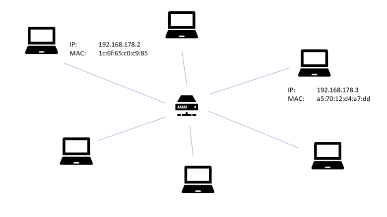
Here we are considering a network consisting of a small number of workstations and one Ethernet switch (in the middle of the diagram). Each workstation is equipped with a network interface card (NIC) which has an Ethernet (MAC) address. Thanks to the switch, Ethernet frames sent out by one NIC can be directly read by any other NIC.
At configuration time, each NIC receives an assigned IP address. This is usually done using a technology like DHCP, but can also be done manually as long as no IP address is used twice.
Now suppose that the workstation with IP address 192.168.178.2 (more precisely: the workstation to which the network interface card with assigned IP address 192.168.178.2 is attached) wishes to send an IP packet to the workstation with IP address 192.168.178.3. It then needs to make several decisions:
- which network interface card should be used to transmit the packet?
- which Ethernet target address should be used?
In the simple case that we consider, the answer to the first question is obvious, as there is only one NIC attached to the workstation, but this question will become more relevant in the more complex setup that we will study later. The second question is more interesting – to answer it, the workstation somehow needs a way to translate an IP address into the MAC address of the corresponding NIC.
To do this, the ARP protocol is at our disposal. ARP is the abbreviation for Address resolution protocol and is defined in RFC 826. ARP messages are designed to travel on top of Ethernet or other link layer protocols. Essentially, the ARP protocol is request-reply based. If a host wishes to translate an IP address into an Ethernet address, it will send an ARP request to all hosts on the local network, using an Ethernet broadcast. This message will contain the own IP and MAC address and the IP address that the host is looking for. Each host on the network will compare the IP address to its own IP address. If they match, it will respond with a reply message that again contains the own IP and MAC address. The requesting host can then use this message to retrieve the correct MAC address and use it for further communication.
Of course this procedure is not repeated every time a host wants to send a packet to another host in the local network. Instead, a host will cache a mapping of IP addresses to Ethernet MAC address in a so called ARP cache. As the assignment of IP addresses to network interface cards can vary over time, entries in this cache typically have a timeout so that they become invalid after some time. On a Linux workstation, the arp command can be used to print the current content of the ARP cache, i.e. the set of hosts to which the workstation has a direct connection that has been recently used. On my PC, the output looks as follows.
$ arp -n
Address                  HWtype  HWaddress           Flags Mask            Iface
192.168.178.1            ether   08:96:d7:75:7e:80   C                     enp4s0
192.168.178.33           ether   ac:b5:7d:34:3a:a6   C                     enp4s0
192.168.178.28           ether   00:11:32:77:fe:46   C                     enp4s0
Here we see that the network card of my PC is able to connect directly to three other hosts on the same Ethernet network. The first one is my router, the second one is a laptop connected to the same router via WLAN (the router actually contains a switch that makes the devices connected via WLAN to appear on the network as an Ethernet device) and the third one is a NAS.
Summarizing, here are the steps that a host would typically take to send an IP packet to another host on the local network.
- Look up the target IP address in the ARP cache
- If there is a match, retrieve the MAC address from the ARP cache entry, assemble an Ethernet frame with that target address and send it
- If there is no match, send an ARP request as broadcast into the local network. Once a reply arrives, add a corresponding entry to the ARP cache. Then proceed as above by assembling and sending the Ethernet frame
- If no ARP reply arrives, give up – this will typically result in an error message like “destination host unreachable”
Note that the ARP protocol is designed to determine the target Ethernet address inside a local network. ARP requests will be dropped at network boundaries. Now, the Internet is by design a network of network – it consists of many small networks that are connected to each other. Obviously, the ARP protocol is no longer sufficient to solve the routing challenge in these more complex networks, and we need additional tools. This will be discussed in the next section.
Routing across network boundaries
For the sake of concreteness, let us again take a look at a slighly modified version of the example network that we have already used earlier in this series.
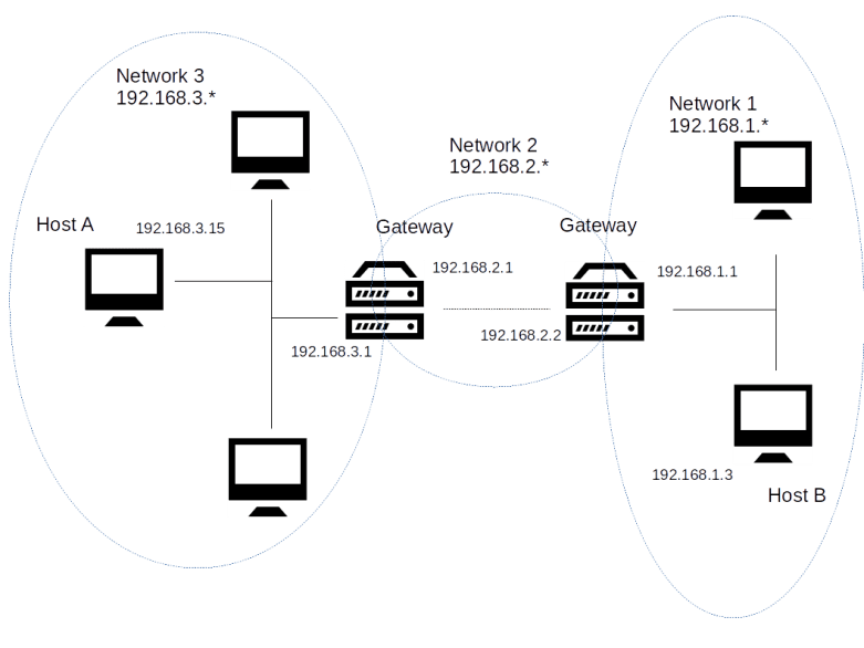
In this example, our entire network is comprised of three different networks, called network 1, network 2 and network 3. In each of these networks, each host is reachable from any other host directly via an Ethernet medium. Thus for the communication within each of these networks, the mechanisms explained in the previous section apply – a host uses the ARP protocol to translate IP addresses into MAC addresses and sends IP messages directly as payload of Ethernet frames.
Now let us walk through the chain of events that takes place when in this topology, host B wishes to send an IP packet to host A. The first thing that host B needs to detect is that host A is not part of the same Ethernet network. To be able to do this, an additional configuration item is used that we have ignored so far – the subnet mask.
When a network interface card is set up, we typically do not only assign an IP address to it, but also a network mask. Technically speaking, a network mask is – as the IP address itself – a sequence of four bytes, using the same decimal dot notation that we use for the IP address. Thus, as the IP address, it is a sequence of 32 bits. We can therefore apply a boolean AND operation to the IP address and the network mask. The result is, by definition, the network part of the IP address, the remaining part is the host part of the IP address. All IP addresses which share a common network part are considered to be part of the same subset, and the standard IP routing algorithms assume that they are connected directly via Ethernet or another link layer protocol.
Let us look at an example to make this clearer. In our case, the network mask for all three subnets is 255.255.255.0. When we take the IP address 192.168.1.3 of host B and apply a logical AND to this and the network mask, we obtain the network part 192.168.1.0, as displayed in the table below.
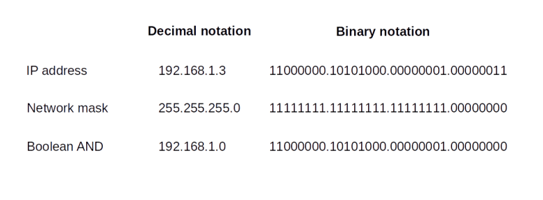
When we apply the same procedure to host A, we obtain the network 192.168.3.0. Thus the two hosts are not in the same subnet, and host B can use that information to determine that a direct routing attempt via ARP will not work (this is actually a bit of a simplification – typically, the host will use an algorithm known as longest match prefix algorithm involving the network mask).
Instead, in order to reach host A, host B will have to make use of a so-called gateway or router. Roughly speaking, a gateway is a host that is connected to more than one network and can therefore transmit or route (hence the name router which is often used as a synonym, even though this is not entirely correct, see RFC 4949 for a discussion of the terminology) packets between the networks.
In our example, there are two gateways. The first gateway connects the networks 1 and 2. It has two network interface cards. The first NIC is connected to network 1 and has the assigned IP address 192.168.1.1. The second NIC attached to this host is part of network 2 and has the assigned IP address 192.168.2.2 (this example makes it clear that, strictly speaking, the IP address is not an attribute of a host but of the network interfaces attached to it).
When host A wishes to send an IP packet to host B, it will send the packet to this gateway via the NIC attached to network 1. As this NIC is on the same Ethernet network, this can be done using the ARP resolution protocol discussed earlier. The gateway will then inspect the destination IP address of the packet and consult a table of possible next stations called the routing table. Based on that table, it will decide that the best next station is the gateway connecting network 2 and network 3. This gateway will finally determine that the destination IP address is part of network 3 to which it is directly attached and eventually deliver the packet to host B.
Thus our IP packet did have to pass several intermediate hosts on its way from source to destination. Each such host is called a hop. The traceroute utility can be used to print out the hops that are required to find a way to a given destination address. Essentially, the way this utility works is as follows. It will send out sequences of packets (typically UDP) towards a given destination, with increasing value of the TTL (time-to-live) field. If the value of this field is n, it will only survice n hops, until it will be dropped. The host dropping the packet will send an ICMP packet back to the host on which traceroute runs. This ICMP packet is used by the utility to determine that the sender of the ICMP packet is part of the route and is sitting at station n in the route. By increasing the TTL further until no packets are dropped anymore, the entire route to the destination can be probed in this way.
Here is the output of a traceroute on the workstation on which I am writing this post.
$ traceroute www.wordpress.com
traceroute to www.wordpress.com (192.0.78.13), 30 hops max, 60 byte packets
 1  fritz.box (192.168.178.1)  2.289 ms  3.190 ms  5.086 ms
 2  dslb-178-004-200-001.178.004.pools.vodafone-ip.de (178.4.200.1)  22.503 ms  24.686 ms  25.227 ms
 3  * * *
 4  * * *
 5  92.79.212.61 (92.79.212.61)  33.985 ms 92.79.212.45 (92.79.212.45)  35.649 ms  36.373 ms
 6  145.254.2.175 (145.254.2.175)  38.205 ms 145.254.2.191 (145.254.2.191)  23.090 ms  25.321 ms
 7  edge-a01.fra.automattic.net (80.81.193.69)  25.815 ms  18.981 ms  19.729 ms
 8  192.0.78.13 (192.0.78.13)  22.331 ms  19.813 ms  19.593 ms
We can see that the first station in the path to the destination http://www.wordpress.com is my local DSL router (192.168.178.1), which, not surprising, acts as a default gateway for my local home network. The DSL router than forwards the packet to the next hop (178.4.200.1), which, judging by its name, is part of the DSL infrastructure of my ISP (Vodafone). The next two lines indicate that for the packets with TTL 3 and 4, the utility did not get an answer, most likely because some firewalls were preventing either the probing UDP packet from reaching its destination or because the ICMP message was not sent or not received. Finally, there are three more hops, corresponding to the TTL values 5,6 and 7, before the final destination is reached.
This sounds simple, but in fact routing is a fairly complex process. In a home network, routing is comparatively easy and the routing table is fairly short (you can use the command route on a Linux system to print out the routing table of your machine). Typically, there are only two entries in the routing table of an ordinary PC at home. One entry tells the operating system that all packets that are targeted to an IP address in the local network are to be sent to the local network interface without any gateway. The second entry is the so-called default gateway and simply defines that all other entries are to be sent to a default router, which is for instance the cable modem or DSL router that you use to connect to your ISP.
However, once we leave a home network, life becomes more complicated as there is typically more than one possible path from a source host to a destination host. Thus a host might have more than one possible choice for the next hop, and a lot hinges on routers correctly building their routing tables. Several routing protocols exist that routers use to exchange information among each other to find the best path to the destination efficiently, like ICMP, OSPF, BGP or IS-IS, see RFC 1812, RFC 1142 or RFC 1247 for more details.
There are many topics related to IP networking and routing that we have not yet discussed, for instance network address translation (NAT), details on the ICPM protocol, CIDR notation and address classes, and IP version 6. Instead of getting further into these details, however, we will devote the next post in this series to a protocol sitting on top of IP – the TCP protocol.
